It’s time to face facts, minidlna and XBMC won’t run at the same time in Raspbmc. The basic UPNP included in Raspbmc won’t work consistently and Raspmc and is not nearly as stable as minidlna. OpenELEC is fast enough, but does not have the expandability of a full linux OS. I need to restart this project.
First thing’s first I’m going to straight up speed this thing up as much as I can. At the base level, this begins with the SD card. I’m going to go from a junk 4gb standard speed SD card to a 8gb SanDisk Ultra 30mb/s SDHC. On this I’m going to install the latest version of Raspian and overclock it to the maximum 1GHz.
First of all, here’s a video of this device in action.
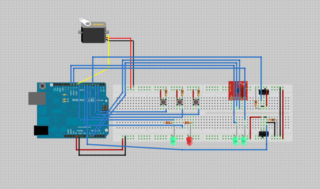
So things are really starting to take shape with the plane (still unnamed…) and I’ve got a really solid framework for an auto-balancing system. Basically the program below maps the x value given from the ADXL335 to a value from 1-180 on the servo. A lot of this code is for debug, but that portion can be switched off.
</pre>
#include <Servo.h>

Servo myservo;

int raw_val;
int ref_val;
int mid_val = 336;

int left_tilt = 260;
int rght_tilt = 405;

int min_switch = 2;
int max_switch = 3;
int mid_switch = 5;
int mode_switch = 4;

int debug_switch = 6;

int bounds_LED = 10;
int mid_LED = 11;

int debug_LED = 7;
int normal_LED = 8;

void setup(){

 pinMode(min_switch, INPUT);
 pinMode(max_switch, INPUT);
 pinMode(mid_switch, INPUT);
 pinMode(debug_switch, INPUT);

 pinMode(mode_switch, INPUT);

 pinMode(bounds_LED, OUTPUT);
 pinMode(mid_LED, OUTPUT);

 pinMode(debug_LED, OUTPUT);
 pinMode(normal_LED, OUTPUT);

 Serial.begin(9600);
 myservo.attach(9);
}

void loop(){
 if (digitalRead(debug_switch) == HIGH) {

 digitalWrite(debug_LED, HIGH);
 digitalWrite(normal_LED, LOW);

 raw_val = analogRead(0);

 if (digitalRead(mode_switch) == HIGH) {

 digitalWrite(bounds_LED, HIGH);
 digitalWrite(mid_LED, LOW);

 Serial.print("BOUNDS MODE: ");

 ref_val = map(raw_val, left_tilt, rght_tilt, 0, 180);

 myservo.write(ref_val);

 if (digitalRead(min_switch) == HIGH){
 Serial.print("LEFT HGH");
 left_tilt = raw_val;
 }

 if (digitalRead(min_switch) == LOW){
 Serial.print("LEFT LOW");
 }

 Serial.print(" , ");

 if (digitalRead(max_switch) == HIGH){
 Serial.print("RGHT HGH");
 rght_tilt = raw_val;
 }

 if (digitalRead(max_switch) == LOW){
 Serial.print("RHGT LOW");
 }

 Serial.print(" , ");

 Serial.print("Left Tilt: ");
 Serial.print(left_tilt);

 Serial.print("Rght Tilt: ");
 Serial.print(rght_tilt);

 }

 if (digitalRead(mode_switch) == LOW) {

 Serial.print("MID MODE:");

 if (digitalRead(mid_switch) == HIGH){
 mid_val = raw_val;
 }

 int MLeft_val = mid_val - 75;
 int MRght_val = mid_val + 75;

 ref_val = map(raw_val, MLeft_val, MRght_val, 0, 180);
 myservo.write(ref_val);

 digitalWrite(bounds_LED, LOW);
 digitalWrite(mid_LED, HIGH);

 Serial.print(" , ");
 Serial.print("Left Most Value: ");
 Serial.print(MLeft_val);
 Serial.print(" , ");
 Serial.print("Rght Most Value: ");
 Serial.print(MRght_val);
 Serial.print(" , ");
 Serial.print(mid_val);

 }
 Serial.print(" , ");
 Serial.print("Raw Value: ");
 Serial.print(raw_val);
 Serial.print(" , ");
 Serial.print("Current Servo Value: ");
 Serial.print(ref_val);

 Serial.println("");
}

 if (digitalRead(debug_switch) == LOW) {

 digitalWrite(debug_LED, LOW);
 digitalWrite(normal_LED, HIGH);

 raw_val = analogRead(0);
 if (digitalRead(mode_switch) == HIGH) {
 digitalWrite(bounds_LED, HIGH);
 digitalWrite(mid_LED, LOW);
 ref_val = map(raw_val, left_tilt, rght_tilt, 0, 180);
 myservo.write(ref_val);
 if (digitalRead(min_switch) == HIGH){
 left_tilt = raw_val;
 }
 if (digitalRead(max_switch) == HIGH){
 rght_tilt = raw_val;
 }
 }

 if (digitalRead(mode_switch) == LOW) {
 if (digitalRead(mid_switch) == HIGH){
 mid_val = raw_val;
 }<a href="https://esologic.com/wp-content/uploads/2012/12/2012-12-27_14-20-51_644.jpg">
</a>
 int MLeft_val = mid_val - 75;
 int MRght_val = mid_val + 75;
 ref_val = map(raw_val, MLeft_val, MRght_val, 0, 180);
 myservo.write(ref_val);
 digitalWrite(bounds_LED, LOW);
 digitalWrite(mid_LED, HIGH);
 }
 }
}
Sorry for the lack of comments in this code, it’s pretty intuitive though, at it’s core its all about the map command.
Here’s a picture of what my desk looks like:
Here’s a picture of the fritzing document, which can be found: here
So although I haven’t written about it yet, right now I’ve gotten a Raspbmc Server up and running along with Minidlna. It works great for about an hour at a time and then it really bogs down. This seems to be caused by a combination of Raspbmc and the hard drive spinning down. My solution is to try OpenELEC, overclock the Raspberry Pi, and change out the SD card for one with a faster read/write speed.
Let me preface this by saying that I am immensely proud of this work. The work up to here is very special and I can only hope that my work going forward is as good as this.
So I’m calling this the “Final Static Prototype” because it’s pretty damn complete for being prototype and it does not move. I intend on making a moving, non-flying prototype sometime in the future. Let’s start out with the video:
Now an explanation for each of the components starting with the controller.
It’s pretty much the same deal I’ve been using this entire time. The program works as follows.
1. The computer sends a delay value and a cycle number
2. The arduino receives that data
3. The arduino sends the debug switch value, the x and y values of the joystick and the pot value.
4. The program renders that information on the program.
Here’s the controller’s source:
//include/define
#include &lt;string.h&gt; // we'll need this for subString
#define MAX_STRING_LEN 20 // like 3 lines above, change as needed.
//Mux control pins
int s0 = 8;
int s1 = 9;
int s2 = 10;
int s3 = 11;
int SIG_pin = 0;
//Shift Register Pins
int SER_Pin = 5; //pin 14 on the 75HC595
int RCLK_Pin = 6; //pin 12 on the 75HC595
int SRCLK_Pin = 7; //pin 11 on the 75HC595
#define number_of_74hc595s 1 //How many of the shift registers - change this
#define numOfRegisterPins number_of_74hc595s * 8 //do not touch
boolean registers[numOfRegisterPins];
//serial stuff
const char EOPmarker = '.'; //This is the end of packet marker
char serialbuf[32]; //This gives the incoming serial some room. Change it if you want a longer incoming.
//other pin setup
int joystick_x;
int joystick_y;
int pot_1;
int debug_switch = 4;
//vars
int sample_delay;
int cycle_number;
void setup(){
//mux setup
pinMode(s0, OUTPUT);
pinMode(s1, OUTPUT);
pinMode(s2, OUTPUT);
pinMode(s3, OUTPUT);
digitalWrite(s0, LOW);
digitalWrite(s1, LOW);
digitalWrite(s2, LOW);
digitalWrite(s3, LOW);
//shift register setup
pinMode(SER_Pin, OUTPUT);
pinMode(RCLK_Pin, OUTPUT);
pinMode(SRCLK_Pin, OUTPUT);
pinMode(0, INPUT);
clearRegisters();
writeRegisters();
//other pin setup
pinMode(debug_switch, INPUT);
Serial.begin(115200);
}
void loop(){ //start of main loop -------------------------------------------
//delay(25);
pin_remap();
if (Serial.available() &gt; 0) {
static int bufpos = 0;
char inchar = Serial.read();
if (inchar != EOPmarker) {
serialbuf[bufpos] = inchar;
bufpos++;
}
else {
serialbuf[bufpos] = 0; //restart the buff
bufpos = 0; //restart the position of the buff
sample_delay = atoi(subStr(serialbuf, &quot;,&quot; , 1));
cycle_number = atoi(subStr(serialbuf, &quot;,&quot; , 2));
serial_handshake();
//delay(100);
}
}
delay(sample_delay);
} //end of main loop --------------------------------------------------------
//start of logic functions ------------------------------------------------
void serial_output_deploy(){
Serial.print(&quot;0&quot;);
Serial.print(&quot;,&quot;);
Serial.print(joystick_x);
Serial.print(&quot;,&quot;);
Serial.print(joystick_y);
Serial.print(&quot;,&quot;);
Serial.print(pot_1);
Serial.print(&quot;,&quot;);
Serial.print(sample_delay);
Serial.print(&quot;,&quot;);
Serial.print(cycle_number);
Serial.println(&quot;&quot;);
}
void serial_output_debug(){
Serial.print(&quot;1&quot;);
Serial.print(&quot;, &quot;);
Serial.print(&quot;Joystick X Axis: &quot;);
Serial.print(joystick_x);
Serial.print(&quot; , &quot;);
Serial.print(&quot;Joystick Y Axis: &quot;);
Serial.print(joystick_y);
Serial.print(&quot; , &quot;);
Serial.print(&quot;Speed Potentiometer: &quot;);
Serial.print(pot_1);
Serial.print(&quot; , &quot;);
Serial.print(&quot;Amount of delay between cycles: &quot;);
Serial.print(sample_delay);
Serial.print(&quot; , &quot;);
Serial.print(&quot;Cycle Number:&quot;);
Serial.print(cycle_number);
Serial.println(&quot;&quot;);
}
void pin_remap(){
joystick_x = map(readMux(15), 0, 1023, 180, 0);
joystick_y = map(readMux(14), 0, 1023, 0, 180);
pot_1 = map(readMux(13), 0, 1023, 0, 179);
}
void serial_handshake(){
if (digitalRead(debug_switch) == HIGH){
serial_output_debug();
setRegisterPin(1, HIGH);
setRegisterPin(2, LOW);
writeRegisters();
}
if (digitalRead(debug_switch) == LOW){
serial_output_deploy();
setRegisterPin(2, HIGH);
setRegisterPin(1, LOW);
writeRegisters();
}
}
//end of logic functions --------------------------------------------------
void clearRegisters(){
for(int i = numOfRegisterPins - 1; i &gt;= 0; i--){
registers[i] = LOW;
}
}
void writeRegisters(){
digitalWrite(RCLK_Pin, LOW);
for(int i = numOfRegisterPins - 1; i &gt;= 0; i--){
digitalWrite(SRCLK_Pin, LOW);
int val = registers[i];
digitalWrite(SER_Pin, val);
digitalWrite(SRCLK_Pin, HIGH);
}
digitalWrite(RCLK_Pin, HIGH);
}
//set an individual pin HIGH or LOW
void setRegisterPin(int index, int value){
registers[index] = value;
}
int readMux(int channel){
int controlPin[] = {s0, s1, s2, s3};
int muxChannel[16][4]={
{0,0,0,0}, //channel 0
{1,0,0,0}, //channel 1
{0,1,0,0}, //channel 2
{1,1,0,0}, //channel 3
{0,0,1,0}, //channel 4
{1,0,1,0}, //channel 5
{0,1,1,0}, //channel 6
{1,1,1,0}, //channel 7
{0,0,0,1}, //channel 8
{1,0,0,1}, //channel 9
{0,1,0,1}, //channel 10
{1,1,0,1}, //channel 11
{0,0,1,1}, //channel 12
{1,0,1,1}, //channel 13
{0,1,1,1}, //channel 14
{1,1,1,1} //channel 15
};
//loop through the 4 sig
for(int i = 0; i &lt; 4; i ++){
digitalWrite(controlPin[i], muxChannel[channel][i]);
}
//read the value at the SIG pin
int val = analogRead(SIG_pin);
//return the value
return val;
}
char* subStr (char* input_string, char *separator, int segment_number) {
char *act, *sub, *ptr;
static char copy[MAX_STRING_LEN];
int i;
strcpy(copy, input_string);
for (i = 1, act = copy; i &lt;= segment_number; i++, act = NULL) {
sub = strtok_r(act, separator, &amp;ptr);
if (sub == NULL) break;
}
return sub;
}
Now for the output simulator (eventually the plane)
This works like the controller with the “handshake” protocol as described above, but it writes to the servos and then sends sensor values. Here’s that source:
//include/define
#include &lt;string.h&gt; // we'll need this for subString
#define MAX_STRING_LEN 20 // like 3 lines above, change as needed.
#include &lt;LiquidCrystal.h&gt; //we'll need this for the lcd
LiquidCrystal lcd(22, 24, 26, 28, 32, 34); //pins for the lcd, I set it up using the ladyada tutorial.
#include &lt;Servo.h&gt;
//inputs
int debug_switch = 7;
//outputs
Servo left_servo;
Servo right_servo;
Servo esc;
int esc_pwm = 6;
int debug_led = 11;
int deploy_led = 12;
//numbers
int left_servo_pos;
int right_servo_pos;
int current;
//serial stuff
const char EOPmarker = '.'; //This is the end of packet marker
char serialbuf[32]; //This gives the incoming serial some room. Change it if you want a longer incoming.
//shift register setup
int SER_Pin = 8; //pin 14 on the 75HC595
int RCLK_Pin = 9; //pin 12 on the 75HC595
int SRCLK_Pin = 10; //pin 11 on the 75HC595
#define number_of_74hc595s 1 //How many of the shift registers - change this
#define numOfRegisterPins number_of_74hc595s * 8 //do not touch
boolean registers[numOfRegisterPins];
void setup(){
//lcd.begin(16, 2);
left_servo.attach(3);
right_servo.attach(5);
esc.attach(6);
current = 0;
pinMode(debug_switch, INPUT);
pinMode(1, INPUT);
pinMode(debug_led, OUTPUT);
pinMode(deploy_led, OUTPUT);
pinMode(SER_Pin, OUTPUT);
pinMode(RCLK_Pin, OUTPUT);
pinMode(SRCLK_Pin, OUTPUT);
pinMode(esc_pwm, OUTPUT);
// for(int i = 0; i &lt; 180; i += 1){
// esc.write(i);
// Serial.println(i);
// delay(15);
// }
clearRegisters();
writeRegisters();
Serial.begin(115200); //changing this to other speeds has not been tested using this meathod
}
void loop() {
if (Serial.available() &gt; 0) {
//lcd.clear();
static int bufpos = 0;
char inchar = Serial.read();
if (inchar != EOPmarker) {
serialbuf[bufpos] = inchar;
bufpos++;
}
else {
serialbuf[bufpos] = 0; //restart the buff
bufpos = 0; //restart the position of the buff
if(digitalRead(debug_switch) == HIGH){
debug();
}
if(digitalRead(debug_switch) != HIGH){
deploy();
}
out_deploy();
}
}
}
// below is just function logic, which I do not fully understand. but it works.
char* subStr (char* input_string, char *separator, int segment_number) {
char *act, *sub, *ptr;
static char copy[MAX_STRING_LEN];
int i;
strcpy(copy, input_string);
for (i = 1, act = copy; i &lt;= segment_number; i++, act = NULL) {
sub = strtok_r(act, separator, &amp;ptr);
if (sub == NULL) break;
}
return sub;
}
void clearRegisters(){
for(int i = numOfRegisterPins - 1; i &gt;= 0; i--){
registers[i] = LOW;
}
}
void writeRegisters(){
digitalWrite(RCLK_Pin, LOW);
for(int i = numOfRegisterPins - 1; i &gt;= 0; i--){
digitalWrite(SRCLK_Pin, LOW);
int val = registers[i];
digitalWrite(SER_Pin, val);
digitalWrite(SRCLK_Pin, HIGH);
}
digitalWrite(RCLK_Pin, HIGH);
}
//set an individual pin HIGH or LOW
void setRegisterPin(int index, int value){
registers[index] = value;
}
void spinto(int target) {
//digitalWrite(led2, LOW);
while(current &gt; target){
Serial.println(current);
esc.write(current);
delay(15);
current--;
}
while(current &lt; target){
Serial.println(current);
esc.write(current);
delay(15);
current++;
}
}
void debug(){
setRegisterPin(2, HIGH);
setRegisterPin(1, LOW);
writeRegisters();
left_servo_pos = atoi(subStr(serialbuf, &quot;,&quot;, 1));
lcd.write(&quot;Lft Servo:&quot;);
lcd.write(subStr(serialbuf, &quot;,&quot;, 1)); //witres the first bit of content before the first comma (or other seperator) to the lcd
left_servo.write(left_servo_pos);
lcd.setCursor(0, 1);
right_servo_pos = atoi(subStr(serialbuf, &quot;,&quot;, 2));
lcd.write(&quot;Rgt Servo:&quot;); //this signifies that the first seperation has occured
lcd.write(subStr(serialbuf, &quot;,&quot;, 2)); //same thing as 2 lines above, but with the second parts. this can be repeated
right_servo.write(right_servo_pos);
analogWrite(esc_pwm, atoi(subStr(serialbuf, &quot;,&quot;, 3)));
}
void deploy(){
setRegisterPin(2, LOW);
setRegisterPin(1, HIGH);
writeRegisters();
left_servo.write(atoi(subStr(serialbuf, &quot;,&quot;, 1)));
right_servo.write(atoi(subStr(serialbuf, &quot;,&quot;, 2)));
analogWrite(esc_pwm, atoi(subStr(serialbuf, &quot;,&quot;, 3)));
}
void out_deploy(){
Serial.print(analogRead(0));
Serial.print(&quot;,&quot;);
Serial.print(analogRead(1));
Serial.print(&quot;,&quot;);
Serial.print(analogRead(2));
Serial.println(&quot;&quot;);
}
//esologic.com
//Thanks to http://arduino.cc/forum/index.php?topic=119429
The visual basic program which I’m calling “Vehicle Companion” can be found here in all of it’s glory. The picture below also shows the whole system.
Now all I need is the money to make this thing wireless because I’ve got a way to make it into a moving prototype using materials I already have. I’ll put a donate button somewhere on this website eventually if you want to help me out.
For my Raspberry Pi Media Server to be able to stream to mobile (a topic I haven’t yet covered here) I need to convert ALL of the video in my family’s 700+ file, 400+ gb, media collection to H.264/MPEG-4 AVC. I recently acquired a hard drive to consolidate and store all of this hard drive on. For the past week or so I’ve been making some progress in converting the video. On my windows tower I’ve been using the program Format Factory to convert the video. I’m running into a few problems with this. For one, my windows computer is my main machine, and multithread converting really bottlenecks it. It also takes a long time – having to watch it while it does it’s thing waiting for it to convert instead of just going to the next set of files is annoying. I could just convert
So I’ve decided to get back into python and write a program that will perfect the conversion process. Like in my PiScanner project, I’ll be using an existing program within python and my code will automate the process.
Goals are as follows:
1. Convert the video
2. Make sets of folders for the video
3. Have it all done on the external HDD
4. Have it be more “efficient” than the setup I’m running now. I.E be able to be on all the time – which shouldn’t be a problem as the server you’re viewing this website on is on all time time and I can just run the script here.
There are probably a million tutorials out there to do this, but as I’m doing it for the second time, I figure that I should probably write it down.
First thing’s first, make sure you’re all updated:
sudo apt-get update
Then install lamp
sudo apt-get install lamp-server^
and run through the install process. Make sure you write all of that info down.
Then download wordpress. Assuming they still have their download architecture the same as the time I’m writing this, you can just use this command.
wget http://www.wordpress.org/latest.tar.gz
And unzip this file.
tar -xzvf latest.tar.gz
You should see a LOT of stuff unzipping.
Then remove the tarball
rm latest.tar.gz
Now you need to create a database.
mysql -u WHATEVER YOUR USERNAME IS -p YOUR PASSWORD
mysql> CREATE DATABASE wordpress;
mysql> GRANT ALL PRIVILEGES ON wordpress_risp.* to "AUSERNAME"@"localhost"
#hit enter and make a new line
 -> IDENTIFIED BY "password";
FLUSH PRIVILEGES;
EXIT
Write down this information.
Next move your wordpress folder to where it’s going to be seen by the web, in my case /opt/bitnami/wordpress/risp
mv wordpress /opt/bitnami/wordpress/risp
rename the file “wp-config-sample.php” to “wp-config.php”
mv wp-config-sample.php wp-config.php
edit it using your favorite text editor, in my case vim
vi wp-config.php
Follow the instructions in the document to add your MySQL DB stuff that you established earlier.
At this point you’re pretty much done. Navigate you localhost/wp-admin/install.php in your favorite browser to set it all up.
To be able to upload images, you will need to run the following command:
sudo chown -R 755 www-data:www-data /var/www
To be able to use custom permalinks within wordpress, we’ll need to make a couple modifications. The first is modify the apahce2 virtual host settings with:
sudo nano /etc/apache2/sites-enabled/000-default
Change the /opt/bitnami/wordpress/ settings so AllowOverride None is set to all like so:
We will also need to give the proper permissions of apache to the .htaccess (found in the root directory of your wordpress install, mine is /opt/bitnami/wordpress/) file by running the following commands:
I’ve made some progress on the RPi Streaming Server.
To replicate this you’ll need to do the following:
1. Install miniDLNA
sudo apt-get install minidlna
2. Edit the config file to how you want it. Edit it using vim
sudo vi /etc/minidlna.conf
3. Here’s what I’m working with, and it works.
# This is the configuration file for the MiniDLNA daemon, a DLNA/UPnP-AV media
# server.
#
# Unless otherwise noted, the commented out options show their default value.
#
# On Debian, you can also refer to the minidlna.conf(5) man page for
# documentation about this file.

# Path to the directory you want scanned for media files.
#
# This option can be specified more than once if you want multiple directories
# scanned.
#
# If you want to restrict a media_dir to a specific content type, you can
# prepend the directory name with a letter representing the type (A, P or V),
# followed by a comma, as so:
#   * "A" for audio    (eg. media_dir=A,/var/lib/minidlna/music)
#   * "P" for pictures (eg. media_dir=P,/var/lib/minidlna/pictures)
#   * "V" for video    (eg. media_dir=V,/var/lib/minidlna/videos)
#
# WARNING: After changing this option, you need to rebuild the database. Either
#          run minidlna with the '-R' option, or delete the 'files.db' file
#          from the db_dir directory (see below).
#          On Debian, you can run, as root, 'service minidlna force-reload' instead.
media_dir=A,/home/pi/stream_files/media/audio
media_dir=P,/home/pi/stream_files/media/pictures
media_dir=V,/home/pi/stream_files/media/video
media_dir=/home/pi/stream_files/media

# Path to the directory that should hold the database and album art cache.
db_dir=/var/lib/minidlna

# Path to the directory that should hold the log file.
#log_dir=/var/log

# Minimum level of importance of messages to be logged.
# Must be one of "off", "fatal", "error", "warn", "info" or "debug".
# "off" turns of logging entirely, "fatal" is the highest level of importance
# and "debug" the lowest.
#log_level=warn

# Use a different container as the root of the directory tree presented to
# clients. The possible values are:
#   * "." - standard container
#   * "B" - "Browse Directory"
#   * "M" - "Music"
#   * "P" - "Pictures"
#   * "V" - "Video"
# if you specify "B" and client device is audio-only then "Music/Folders" will be used as root
#root_container=.

# Network interface(s) to bind to (e.g. eth0), comma delimited.
#network_interface=

# IPv4 address to listen on (e.g. 192.0.2.1).
#listening_ip=

# Port number for HTTP traffic (descriptions, SOAP, media transfer).
port=8200

# URL presented to clients.
# The default is the IP address of the server on port 80.
#presentation_url=http://example.com:80

# Name that the DLNA server presents to clients.
#friendly_name=

# Serial number the server reports to clients.
serial=12345678

# Model name the server reports to clients.
#model_name=Windows Media Connect compatible (MiniDLNA)

# Model number the server reports to clients.
model_number=1

# Automatic discovery of new files in the media_dir directory.
#inotify=yes

# List of file names to look for when searching for album art. Names should be
# delimited with a forward slash ("/").
album_art_names=Cover.jpg/cover.jpg/AlbumArtSmall.jpg/albumartsmall.jpg/AlbumArt.jpg/albumart.jpg/Album.jpg/album.jpg/Folder.jpg/folder.jpg/Thumb.jpg/thumb.jpg

# Strictly adhere to DLNA standards.
# This allows server-side downscaling of very large JPEG images, which may
# decrease JPEG serving performance on (at least) Sony DLNA products.
#strict_dlna=no

# Support for streaming .jpg and .mp3 files to a TiVo supporting HMO.
#enable_tivo=no

# Notify interval, in seconds.
#notify_interval=895

# Path to the MiniSSDPd socket, for MiniSSDPd support.
#minissdpdsocket=/run/minissdpd.sock
You can grab the file itself here. The only thing that’s different is where I put the media directories. The rest of the instructions are still in the .conf, it’s much simpler than mediatomb for example.
Here’s a video of the whole thing working on 3 devices!
Once those are installed you can start trying to play videos off of the usb drive (eventually the thumb drive will be replaced with a large hdd
I’ll be using filezilla to transfer to and from the pi.
Check out the video below to see omxplayer in action:
Edit: The upload failed and I forgot to check on it. Come back soon for the video.
I’m choosing to debug my Pi over composite. The reason being is because I’m going to be working a lot with video outputs, and I don’t have a second hdmi ready monitor. I’m going to be using the EasyCAP usb video capture card. This will also give me the ability to record what i’m seeing as well. This 100% better / much more efficient than buying a second monitor and filming on it. Of course when this is ready for implementation, it will be plugged into a television with HDMI so the picture will be amazing.
The goal of this is to become independent from cable TV while still being able to do all of the same things we would with a cable service – I.E still consume content in the living room on the television.
It should also improve upon the experience. I want to be able to stream content from the Pi to any capable device. That list includes but is not limited to:
1. Windows XP
2. Windows 7
3. Linux Debian
4. Linux Ubuntu
5. iOS 6 (ipad)
6. iOS 5.3 (ipod Touch)
7. OSX and up
8. Android "Gingerbread" and up
I’ll be working on this post most of today, so they’ll be a few posts coming.