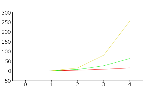
This is a much more refined version of that graph I created earlier.
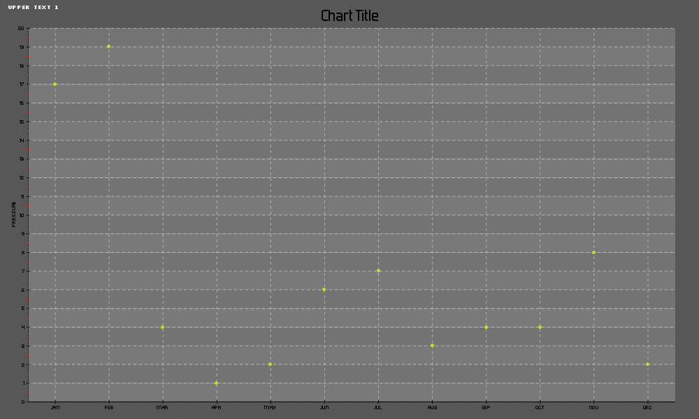
This one is much more detailed, and the sizes of the graph can easily be controlled with the imageSizeX and Y Vals.
This program will render:
<?php
/* CAT:Scaling */

/* pChart library inclusions */
include("/srv/www/lib/pChart/class/pData.class.php");
include("/srv/www/lib/pChart/class/pDraw.class.php");
include("/srv/www/lib/pChart/class/pImage.class.php");

$imageSizeXXal = 1000;
$imageSizeYVal = 600;

/* Create and populate the pData object */
$MyData = new pData();
$MyData->addPoints(array(17,19,4,1,2,6,7,3,4,4,8,2),"Pressure");
$MyData->setSerieDrawable("Pressure",FALSE);
$MyData->setAxisName(0,"Temperatures");

$MyData->addPoints(array("Jan","Feb","Mar","Apr","May","Jun","Jul","Aug","Sep","Oct","Nov","Dec"),"Labels");
$MyData->setSerieDescription("Labels","Months");
$MyData->setAbscissa("Labels");

/* Create the pChart object */
$myPicture = new pImage($imageSizeXXal,$imageSizeYVal,$MyData); //size of the graph box

/* Draw the background */
$Settings = array("R"=>84, "G"=>84, "B"=>84, "Dash"=>1, "DashR"=>95, "DashG"=>95, "DashB"=>95);
$myPicture->drawFilledRectangle(0,0,$imageSizeXXal+5,$imageSizeYVal,$Settings); //size of the grey background

/* Write the picture title */
$myPicture->setFontProperties(array("FontName"=>"/srv/www/lib/pChart/fonts/Silkscreen.ttf","FontSize"=>6));
$myPicture->drawText(10,13,"Upper Text 1",array("R"=>255,"G"=>255,"B"=>255));

/* Write the chart title */
$myPicture->setFontProperties(array("FontName"=>"/srv/www/lib/pChart/fonts/Forgotte.ttf","FontSize"=>11));
$myPicture->drawText($imageSizeXXal/2,30,"Chart Title",array("FontSize"=>20,"Align"=>TEXT_ALIGN_BOTTOMMIDDLE));

/* Define the 2nd chart area */
$myPicture->setGraphArea(40,40,$imageSizeXXal-35,$imageSizeYVal-25); //top left, then bottom right conrner of box
$myPicture->setFontProperties(array("FontName"=>"/srv/www/lib/pChart/fonts/pf_arma_five.ttf","FontSize"=>6));

/* Draw the scale */
$scaleSettings = array("DrawSubTicks"=>TRUE,"CycleBackground"=>TRUE);
$MyData->setSerieDrawable("Temperature",FALSE);
$MyData->setSerieDrawable("Pressure",TRUE);
$MyData->setAxisName(0,"Pressure");
$myPicture->drawScale($scaleSettings);
$myPicture->drawPlotChart();

/* Render the picture (choose the best way) */
$myPicture->autoOutput();
?>
This image:
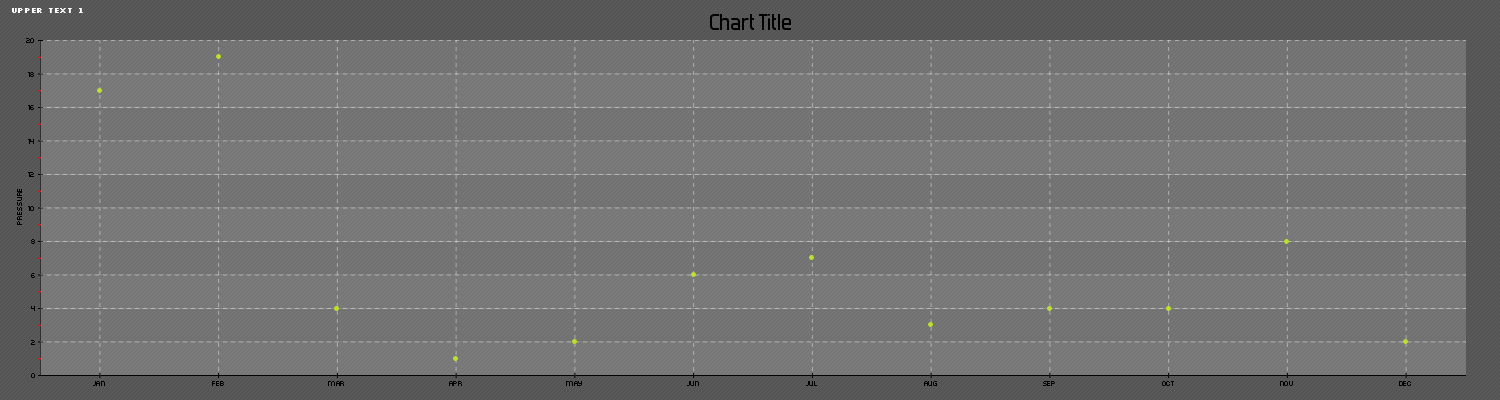
And by modifying the values mentioned above to:
$imageSizeXXal = 1500;
$imageSizeYVal = 400;
You will get this image: