For the past while I’ve been working on a major redesign of my high performance gpu cooler project.
The rapid ascent of the LLM into the collective consciousness has sent the big players into a frenzy over datacenter GPUs. This is putting accelerating downward pressure on the price of all used compute GPUs, even the historically pricey stuff. P100s can be had for ~$100, V100 16GB are selling for ~$500, any day now the lower VRAM Ampere cards are going to drop below $1000…
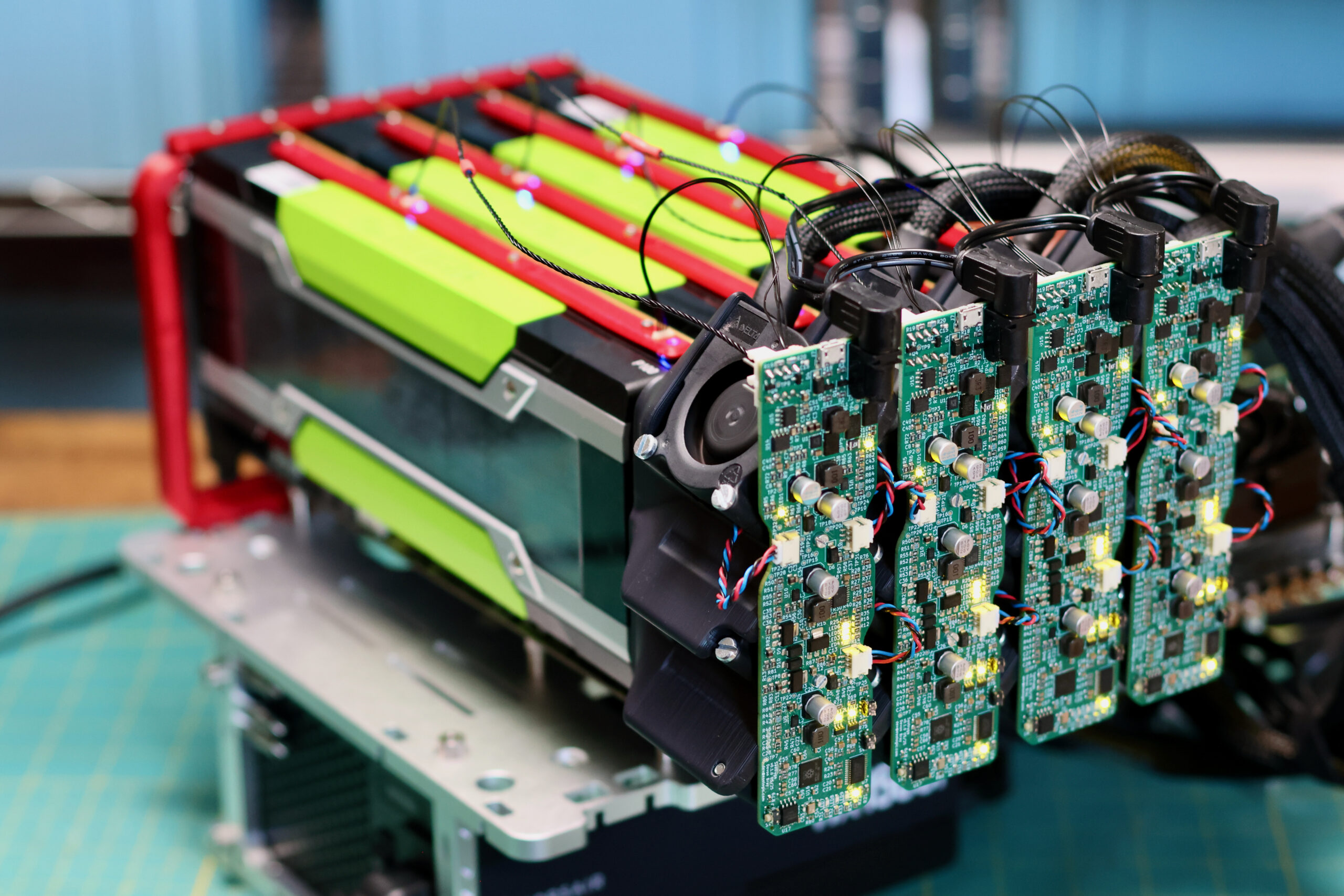
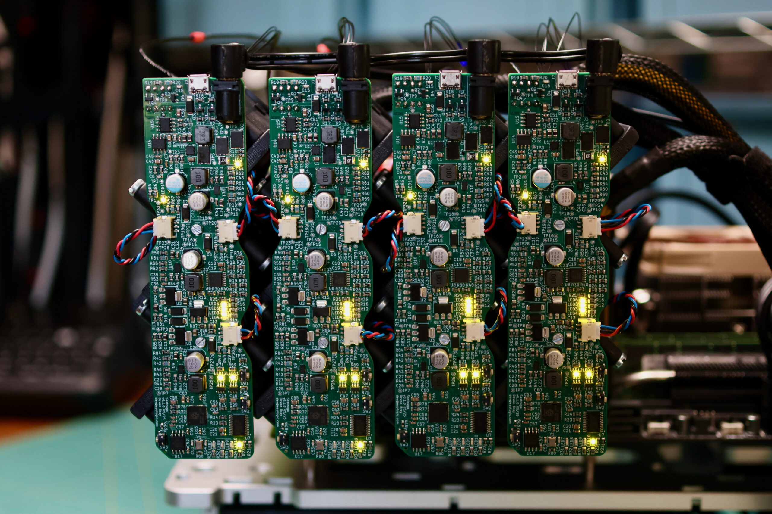
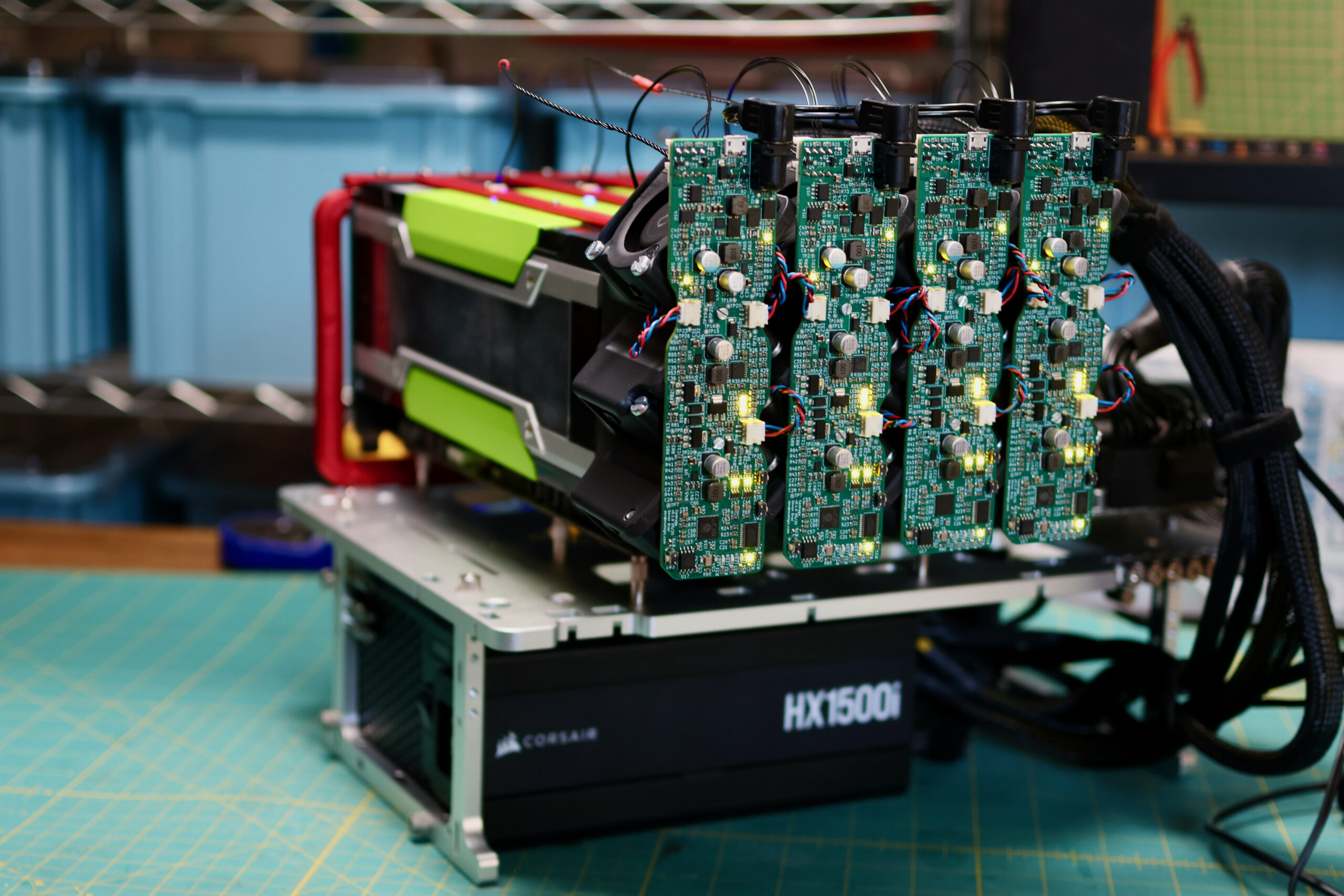
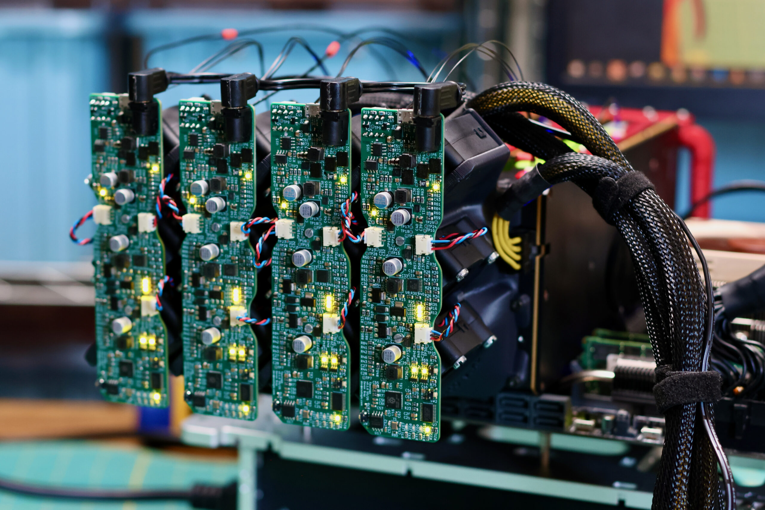
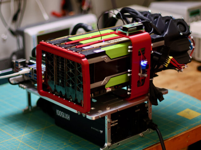
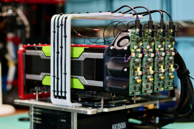
We need a new cooler that can support any of these 300W GPUs, can be installed as densely as the cards, and is easy on the ears for homelab use. Pictured below are four prototype coolers installed on Tesla P100s: