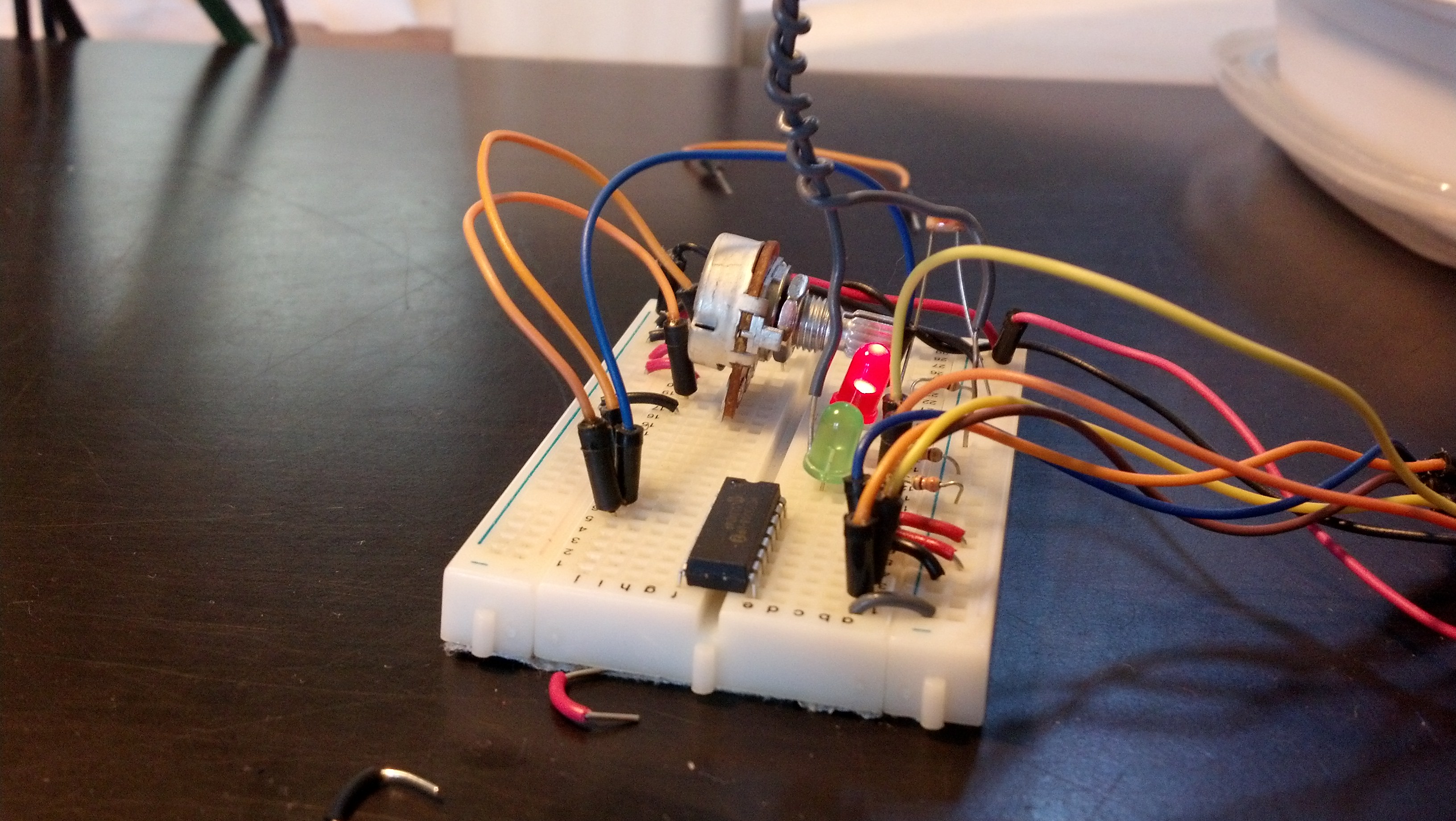
I’m in a hotel trying to occupy myself with something interesting so I’ve decided to work on this. I had to re-image the SD card I’ve been developing this project on, but I saved to code so there’s no problem there. Now I need to re-install all the basic packages.
First I need to get the components of a LAMP server with the following commands:
sudo apt-get install apache2
sudo apt-get install mysql-server
sudo apt-get install php5
sudo apt-get install php5-server
sudo apt-get install php5-mysql
Once you get the mysql server setup, you’ll need to create a database and tables in mysql.
To create the database you’ll be using run the following command:
CREATE DATABASE piplanter;
And then grant the proper privileges to use later with the command:
mysql> mysql> GRANT ALL PRIVILEGES ON piplanter.* TO 'user'@'localhost' IDENTIFIED BY 'pass';
FLUSH PRIVILEGES;
Then we can enter the database and create a table:
USE piplanter;
CREATE TABLE piplanter_table_01(Sample_Number INT NOT NULL AUTO_INCREMENT PRIMARY KEY, Time VARCHAR(100), Temp_F VARCHAR(100), LDR_V VARCHAR(100) );
Now we need to set up the specific libraries for python the first of which being spidev, the spi tool for the raspberry pi which we can grab from git using the following commands:
sudo apt-get install git
git clone git://github.com/doceme/py-spidev
cd py-spidev/
sudo apt-get install python-dev
sudo python setup.py install
You also need to (copied from http://scruss.com/blog/2013/01/19/the-quite-rubbish-clock/):
As root, edit the kernel module blacklist file:
sudo vi /etc/modprobe.d/raspi-blacklist.conf
Comment out the spi-bcm2708 line so it looks like this:
#blacklist spi-bcm2708
Save the file so that the module will load on future reboots. To enable the module now, enter:
sudo modprobe spi-bcm2708
We will also need WiringPi:
sudo apt-get install python-imaging python-imaging-tk python-pip python-dev git
sudo pip install spidev
sudo pip install wiringpi
Then you need to get APscheduler, the timing program used to execute the incremental timing with the following commands:
wget https://pypi.python.org/packages/source/A/APScheduler/APScheduler-2.1.0.tar.gz
sudo tar -xzvf APScheduler-2.1.0.tar.gz
python setup.py install
You will need mysqldb to interface python and mysql:
sudo apt-get install python-mysqldb
Once you reboot, the following program should work:
#Timing setup
from datetime import datetime
from apscheduler.scheduler import Scheduler
import time
import datetime
import sys
now =datetime.datetime.now()
import logging #if you start getting logging errors, uncomment these two lines
logging.basicConfig()
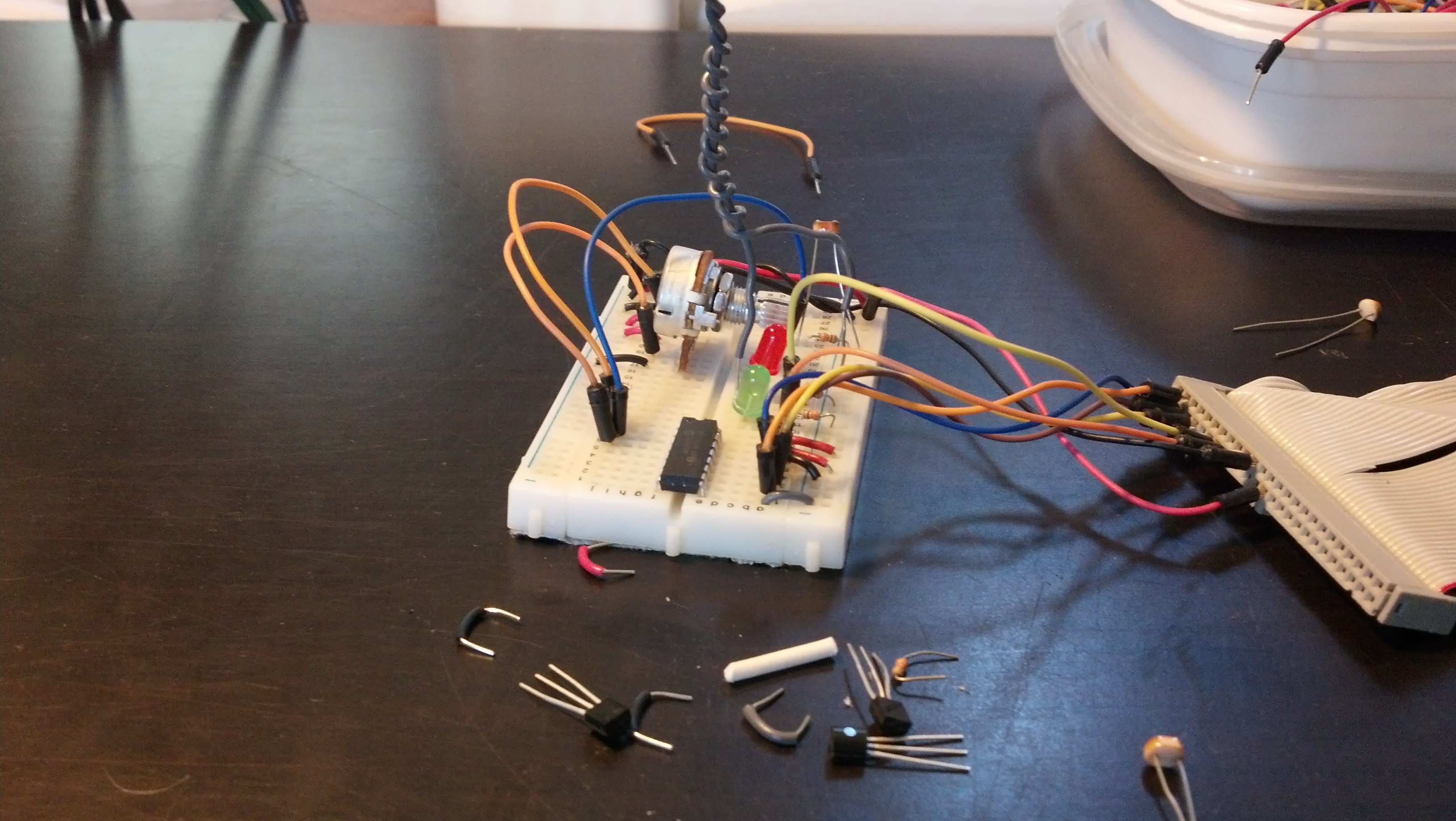
#GPIO setup
import RPi.GPIO as GPIO
GPIO.setmode(GPIO.BOARD)
GPIO.cleanup()
pin = 26 #pin for the adc
GPIO.setup(pin, GPIO.OUT)
led1 = 11 #pin for the short indicator led
GPIO.setup(led1, GPIO.OUT)
led2 = 13 #pin for other long indicator led
GPIO.setup(led2, GPIO.OUT)
#the adc's SPI setup
import spidev
spi = spidev.SpiDev()
spi.open(0, 0)
import MySQLdb
con = MySQLdb.connect('localhost','piplanter_user','piplanter_pass','piplanter');
cursor = con.cursor()
#fuction that can read the adc
def readadc(adcnum):
# read SPI data from MCP3008 chip, 8 possible adc's (0 thru 7)
if adcnum > 7 or adcnum < 0:
return -1
r = spi.xfer2([1, 8 + adcnum << 4, 0])
adcout = ((r[1] & 3) << 8) + r[2]
return adcout
def rapidSample():
sampleTime = time.ctime()
sampleTemp1 = (((readadc(0)*3.3)/1024)/(10.0/1000)) #this translates the analog voltage to temperature in def F
sampleLght1 = readadc(1)
samplePot1 = readadc(2)
GPIO.output(led1, True) #turns the led on
time.sleep(.1) #sleeps a little bit so you can see the LED on
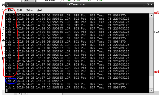
print "Job 1", sampleTime,"LDR:",sampleLght1 ,"Pot:",samplePot1,"Temp:",sampleTemp1 #prints the debug info
cursor.execute("INSERT INTO piplanter_table_02(Time,Temp_F,LDR_V) VALUES(%s,'%s','%s')",(sampleTime,sampleTemp1,sampleLght1))
con.commit() #this is important for live updating
time.sleep(.1)
GPIO.output(led1, False) #turns the led off
def slowSample():
sampleTime = time.ctime()
sampleTemp1 = (((readadc(0)*3.3)/1024)/(10.0/1000)) #this translates the analog voltage to temperature in def F
sampleLght1 = readadc(1)
samplePot1 = readadc(2)
GPIO.output(led2, True) #turns the led on
time.sleep(5)
print "Job 2", sampleTime,"LDR:",sampleLght1 ,"Pot:",samplePot1,"Temp:",sampleTemp1 #prints the debug info
cursor.execute("INSERT INTO piplanter_table_03(Time,Temp_F,LDR_V) VALUES(%s,'%s','%s')",(sampleTime,sampleTemp1,sampleLght1))
con.commit() #this is important for live updating
time.sleep(5)
GPIO.output(led2, False) #turns the led on
if __name__ == '__main__':
#the following 3 lines start up the interval job and keep it going
scheduler = Scheduler(standalone=True)
scheduler.add_interval_job(rapidSample, minutes=1)
scheduler.add_interval_job(slowSample, hours=1)
scheduler.start()
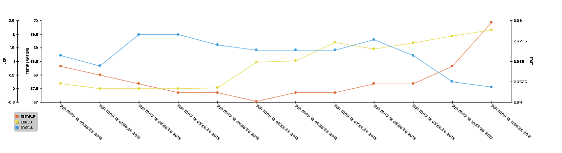
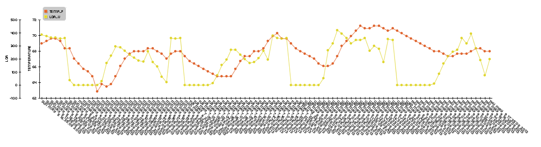
And there you go! The program should log data every minute and then every hour to two different tables. To view those data sets as php tables you can use this php script:
<?php
mysql_connect("localhost", "piplanter_user","piplanter_pass") or die ("Could not connect: " . mysql_error());
mysql_select_db("piplanter");

$result = mysql_query("SELECT * FROM piplanter_table_02");

echo "<table border='1'>
<tr>
<th>Sample_Number</th>
<th>Time</th>
<th>Temp F</th>
<th>LDR Value V</th>
</tr>";

while($row = mysql_fetch_array($result)){
	echo"<tr>";
	echo"<td>" . $row['Sample_Number'] . "</td>";
	echo"<td>" . $row['Time'] . "</td>";
	echo"<td>" . $row['Temp_F'] . "</td>";
	echo"<td>" . $row['LDR_V'] . "</td>";
	echo"</tr>";
}

echo "</table>";
mysql_close($con);
?>
Sometime later I’ll get to graphing the data.