In working on an project for work, I have figured out the hard way that Electron has to be started from a terminal session on your target device (ie the computer it is to be viewed on). I am developing an embedded system based on the Raspberry Pi that does not take user input but displays information on a screen.
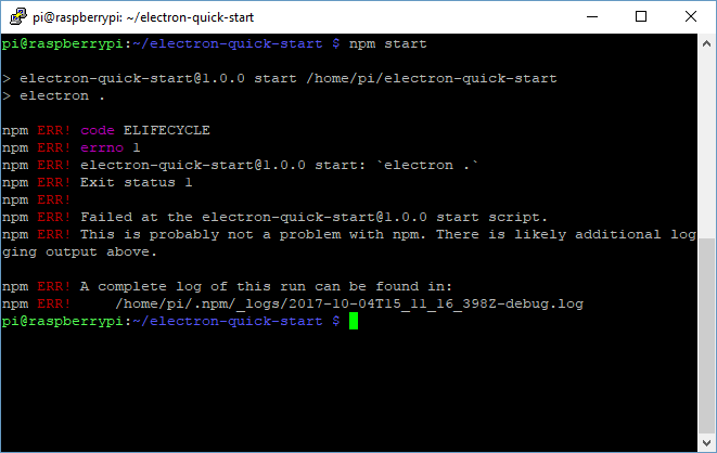
Upon downloading the electron-quick-start example, everything installs correctly without error and can be done remotely via SSH. Upon running with npm start, the following error is thrown.
> electron-quick-start@1.0.0 start /home/pi/electron-quick-start
> electron .

npm ERR! code ELIFECYCLE
npm ERR! errno 1
npm ERR! electron-quick-start@1.0.0 start: `electron .`
npm ERR! Exit status 1
npm ERR!
npm ERR! Failed at the electron-quick-start@1.0.0 start script.
npm ERR! This is probably not a problem with npm. There is likely additional logging output above.

npm ERR! A complete log of this run can be found in:
npm ERR!     /home/pi/.npm/_logs/2017-10-04T15_11_16_398Z-debug.log
I spent most of the evening trying to debug npm ERR! code ELIFECYCLE to no avail. On a lark, I connected a keyboard to the device and ran npm start and it ran without error. Sigh.
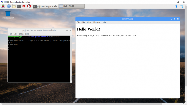
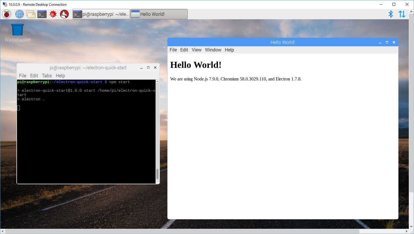
The remote development alternative for doing this is to use Remote Desktop Connection a client comes bundled in with windows. The software can be installed on the remote system (the Raspberry Pi) using apt-get install xrdp. Upon connecting, opening up a shell in the RDP client, and running npm start, the example application works just fine.
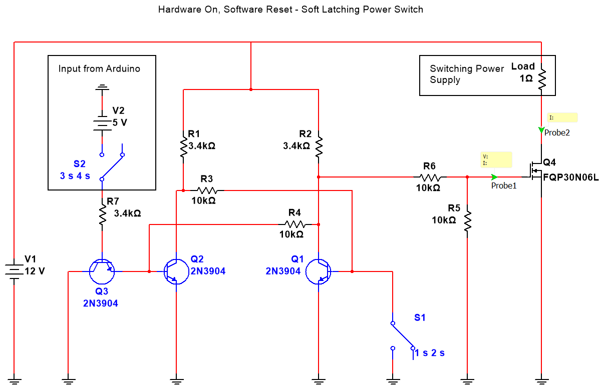
This circuit aims to replace a traditional toggle switch for switching large amounts of current. Instead of the bulky and expensive traditional toggle switch, this circuit allows for a cheap pushbutton, and a few transistors and resistors to be used and have the same effect.
For my application, I wanted a way to have the circuit draw very little curren
t when in the off state, be able to be powered on with a pushbutton, and then turned off through software on the Arduino.
Here is the circuit diagram:
Here’s a video of the circuit in operation:
The code running on the Arduino is very simple:
int button = 3;
int led = 2;

void setup() {
  pinMode(button, INPUT);
  pinMode(led, OUTPUT);

  digitalWrite(led, LOW);
}

void loop() {
  if (digitalRead(button)) {
    digitalWrite(led, HIGH);
  }
}
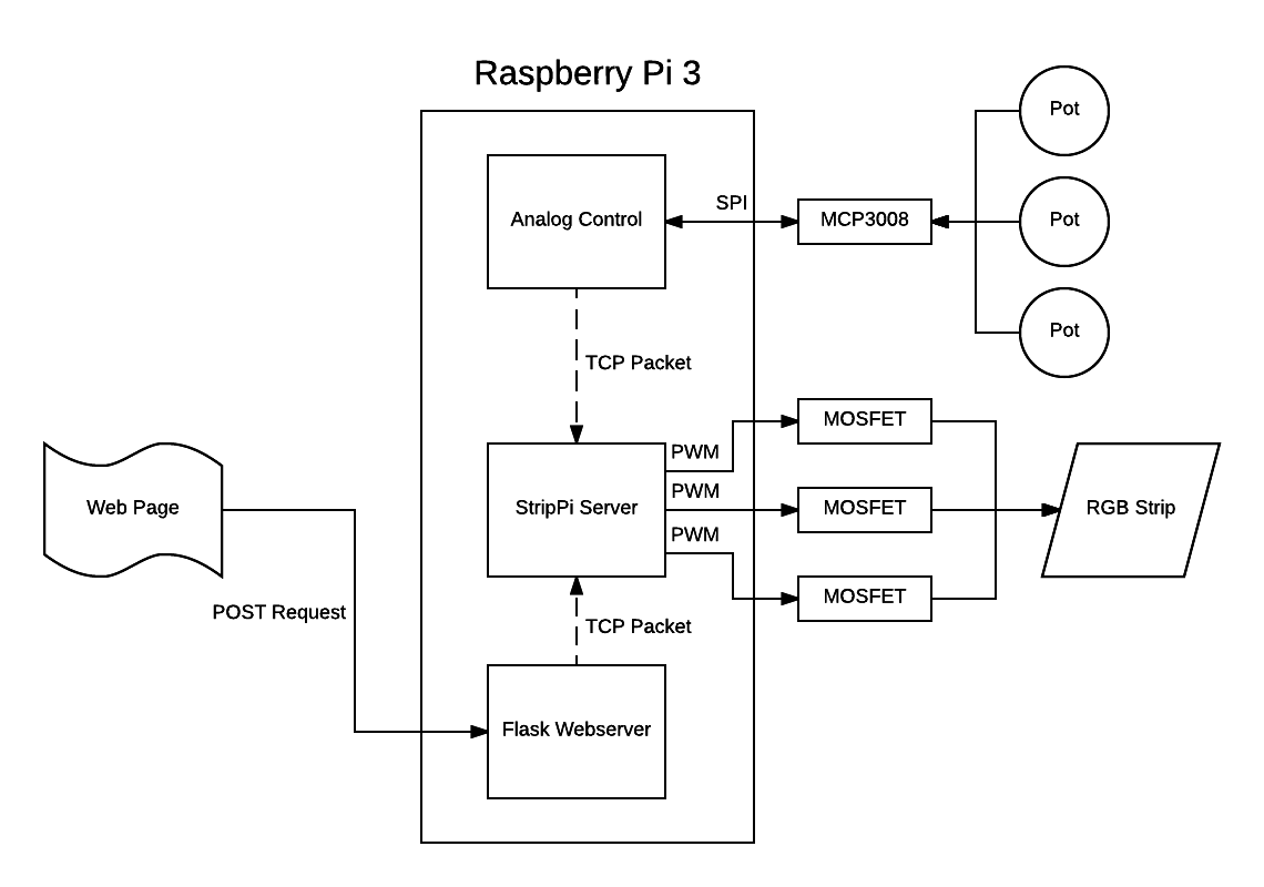
I’m constantly loosing the remote for my RGB LED strip lights, and I have a few days for spring break, time to get hacking. Here’s a demo and explanation video:
I don’t mention it in the video, but the cool part of this project is how the different processes communicate with each other. Rather than interacting with the different processes through pipes, or something like stdin, I’ve decided to use a TCP websocket server:
Processes on the device send RGB values to the Strip Server via a TCP packet. This very very easy to implement, and almost all of the hard work is taken care of via the socketserver module included in python3. This also allows for interactions with that main process (the StripPi Server process) to take place off of the Raspberry Pi as well. I plan on writing an Alexa integration for this project moving forward, and this should make that a lot easier.
The analog to digital conversion is handled by an MCP3008, exactly the same way as I did it here.
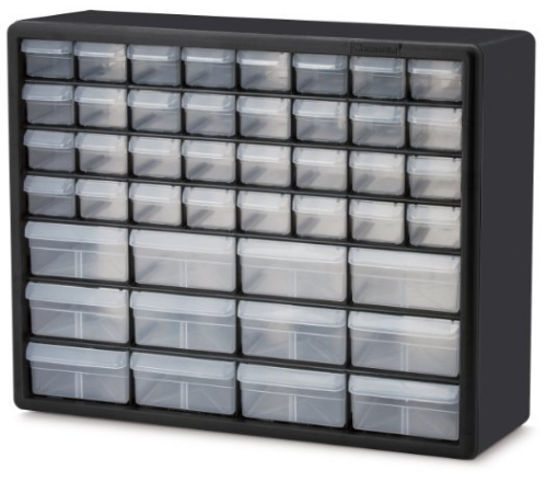
I use these Akro-Mils 10144 D sets of drawers to keep my various electronics components organized. They’re cheap, reasonable quality, but most importantly inexpensive.
Something that I find myself doing a lot is transferring individual drawers around. For example, I have a specific drawer that holds short jumper wires for breadboards. Sometimes I bring this drawer up to campus for working in the lab. Same goes for my misc-resistor drawer. It’s much easier to move the drawer rather than re-packing it.
The problem is that these are open drawers! They don’t have lids, so what I’ll do is put it in a ziplog bag and throw it into my backpack. This is a bad solution, I have a 3D printer, time to get CADing.
I wanted the drawer to be able to lock in place, so it wouldn’t slide out of the holder while in transit, here is a video of the locking mechanism in action:
As I iterated on this design, it became clear that I could get away with a pretty thin wall thickness, and that extending the slot cut made it much much easier to flex the locking mechanism, so the grab point on the outer surface became unnecessary.
Annoyingly, I couldn’t figure out a good solution to be able to use this part without having to use supports.
I recently purchased a Prusa i3 MK2 and it is glorious. The price was right, the assembly was straightforward and the print quality is probably better than I will ever need. After printing the requisite amount of dogs and other figurines, it’s time to start using this tool to improve my life.
I store a lot of my equipment on wire shelves. They’re cheap, easy to move around, and pretty strong. They can hold a lot of stuff, which means I keep a lot on them, and space, much like in the rest of my apartment, is limited. The server that is hosting this webpage lives on one of these shelves, and sometimes I have to manually work on it with a keyboard and monitor. It is a pain to have to dig out a keyboard, but it’s also not worth it to have a keyboard permanently on the shelf taking up space. That desire to maximize space is the motivation behind this project.
This was one of those rare times where I had a hunch, followed it, and had a great result.
So for a project I’m working on for school, we have a robot with multiple composite video cameras onboard. We will be using those cameras seen on DIY drones or in simple security systems. We will be transmitting this video feed via a 5.8GHz video transmitter meant for a drone. We want the operator to be able to switch which feed they’re viewing at a given time, but we don’t want to have to use 3 transmitters and receivers. So to get around this, I thought we might just connect video feeds to a simple analog multiplexer I had laying around from a previous project and see if you could switch the feed that way. Turns out, you totally can. Here’s the eventual block diagram of this part of our project if you’re interested:
The following is the code running on the arduino. Remember, this isn’t doing anything special other than driving the mux:
#define NUMSELECTS 4

int s0 = 2;
int s1 = 3;
int s2 = 4;
int s3 = 5;

int selects[NUMSELECTS] = {s0, s1, s2, s3};
int select_state[NUMSELECTS] = {0, 0, 0, 0};

void setup()
{
  Serial.begin(9600);
  for (int index = 0; index < NUMSELECTS; index++)
  {
    pinMode(selects[index], OUTPUT);
    digitalWrite(selects[index], select_state[index]);
  }
}

void loop()
{
  if (Serial.available() > 0)
  {
    char inchar = Serial.read(); //assigns one byte (as serial.read()'s only input one byte at a time
    switch(inchar)
    {
      case '0':
        Serial.println("Switching to video signal 0");
        select_state[0] = 0;
        select_state[1] = 0;
        select_state[2] = 0;
        select_state[3] = 0;
        write_selects();
        break;
      case '1':
        Serial.println("Switching to video signal 1");
        select_state[0] = 1;
        select_state[1] = 0;
        select_state[2] = 0;
        select_state[3] = 0;
        write_selects();
        break;
       default:
        Serial.println("Bad input");
        break;
    }
  }
}

void write_selects()
{
  for (int index = 0; index < NUMSELECTS; index++)
  {
    digitalWrite(selects[index], select_state[index]);
  }
}
For another project I’m currently working on, I need a way to control multiple microcontrollers in a multi-point, multi-drop network configuration. Luckily, we live in amazing times. As I write this, you you can buy a fully assembled breakout board for the MAX485 chip from Maxim Integrated for a mere $0.45 USD shipped from China.
RS485 is an old protocol, but is the logical next step for devices I’m already communicating with via RS232. For this example, I’m using 4 Arduino boards of various types.
An Arduino Micro as the master
2 Slave Arduino Leonardos
1 Slave Arduino Pro Mini (5v)
Here is a video of the setup:
The schematic is really straightforward as well. The only tricky bit is that I’m using a software serial port on each of the Arduinos for ease of debugging. Here’s a schematic:
The code to acomplish this is really intuitive as well.
Here is the code for the master Arduino:
#include <SoftwareSerial.h>

int MAX485_Receiver_Output_PIN = 10;
int MAX485_Driver_Input_PIN = 11;
int MAX485_Driver_Output_Enable_PIN = 12;

int debug_led = 13;

SoftwareSerial software_serial (MAX485_Receiver_Output_PIN, MAX485_Driver_Input_PIN); // RX, TX

void setup()
{
  Serial.begin(9600); // begin hardware serial
  software_serial.begin(9600); // begin software serial

  pinMode(MAX485_Driver_Output_Enable_PIN, OUTPUT);
  digitalWrite(MAX485_Driver_Output_Enable_PIN, HIGH); // this disables Receiver Output Enable and enables Driver Output Enable
}

void loop()
{

  byte to_send = 0; // declare the byte to be sent to the slaves though, init as 0
  int rate;

  while (true)
  {
    // invert the byte to be sent
    if (to_send == 1) to_send = 0;
    else if (to_send == 0) to_send = 1;

    Serial.print("Sending: ");
    Serial.println(to_send);

    digitalWrite(debug_led, to_send);

    rate = map(analogRead(5), 0, 1023, 0, 1000);

    software_serial.write(to_send); // send our byte out to the MAX485

    delay(rate);
  }
}
This is the code for the slave Arduinos:
#include <SoftwareSerial.h>

int MAX485_Receiver_Output_PIN = 10;
int MAX485_Driver_Input_PIN = 11;
int MAX485_Driver_Output_Enable_PIN = 12;

int debug_led_PIN = 9;

SoftwareSerial software_serial (MAX485_Receiver_Output_PIN, MAX485_Driver_Input_PIN); // RX, TX

void setup()
{
  software_serial.begin(9600); // begin software serial

  pinMode(MAX485_Driver_Output_Enable_PIN, OUTPUT);
  digitalWrite(MAX485_Driver_Output_Enable_PIN, LOW);

  pinMode(debug_led_PIN, OUTPUT);

}

void loop() // run over and over
{
  byte k;

  if (software_serial.available() > 0) // make sure there is something to read
  {
    k = software_serial.read(); // read in a single byte from the serial port
    digitalWrite(debug_led_PIN, k);
  }
}
#include <SoftwareSerial.h>
int MAX485_Receiver_Output_PIN = 10;
int MAX485_Driver_Input_PIN = 11;
int MAX485_Driver_Output_Enable_PIN = 12;
int debug_led_PIN = 9;
SoftwareSerial software_serial (MAX485_Receiver_Output_PIN, MAX485_Driver_Input_PIN); // RX, TX
void setup()
{
software_serial.begin(9600); // begin software serial
pinMode(MAX485_Driver_Output_Enable_PIN, OUTPUT);
digitalWrite(MAX485_Driver_Output_Enable_PIN, LOW);
pinMode(debug_led_PIN, OUTPUT);
}
void loop() // run over and over
{
byte k;
if (software_serial .available() > 0) // make sure there is something to read
{
k = software_serial.read(); // read in a single byte from the serial port
digitalWrite(debug_led_PIN, k);
}
}
In subsequent posts, things will start getting more advanced. For now however this should be enough to start from scratch.