Here’s a video:
Here are some images: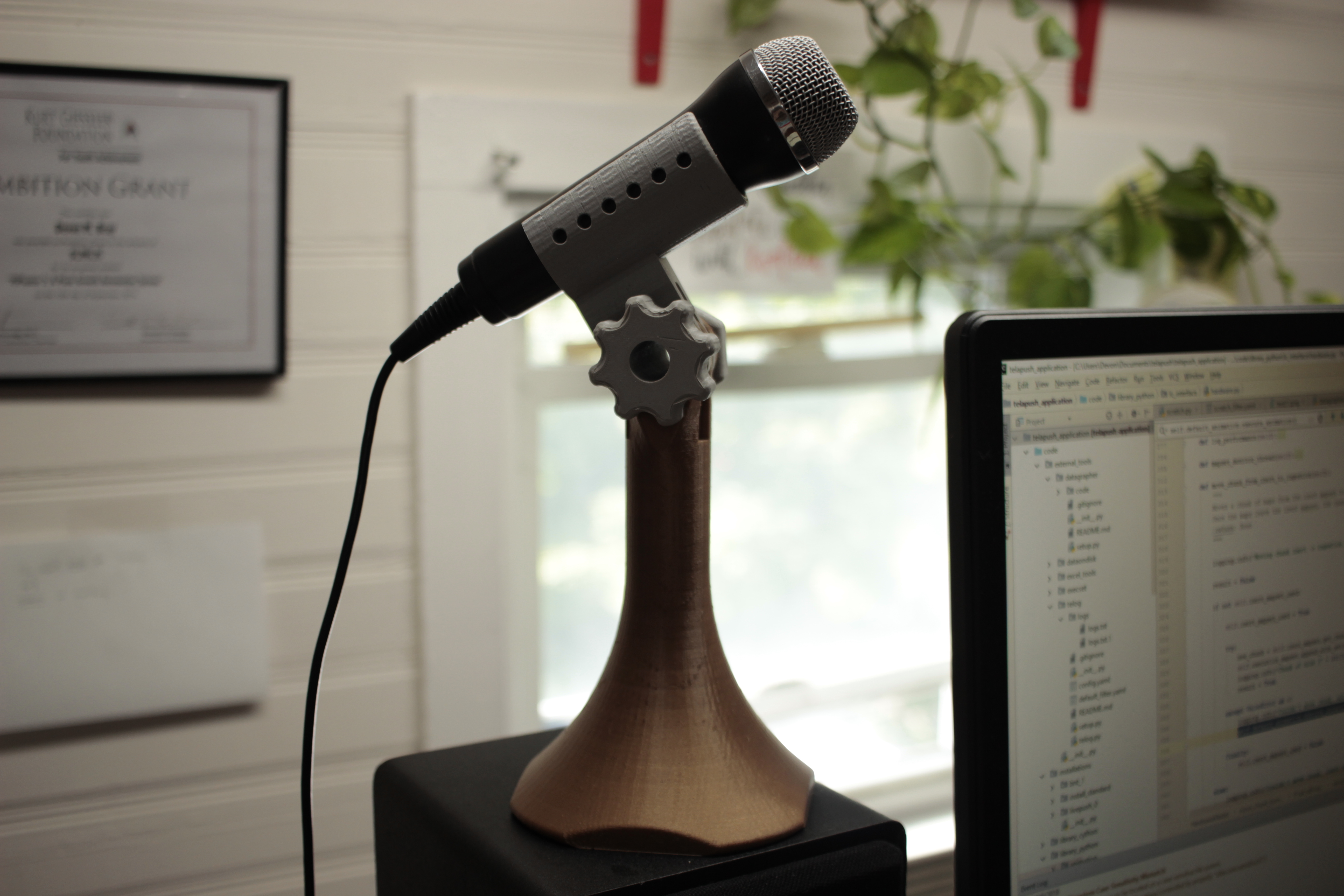
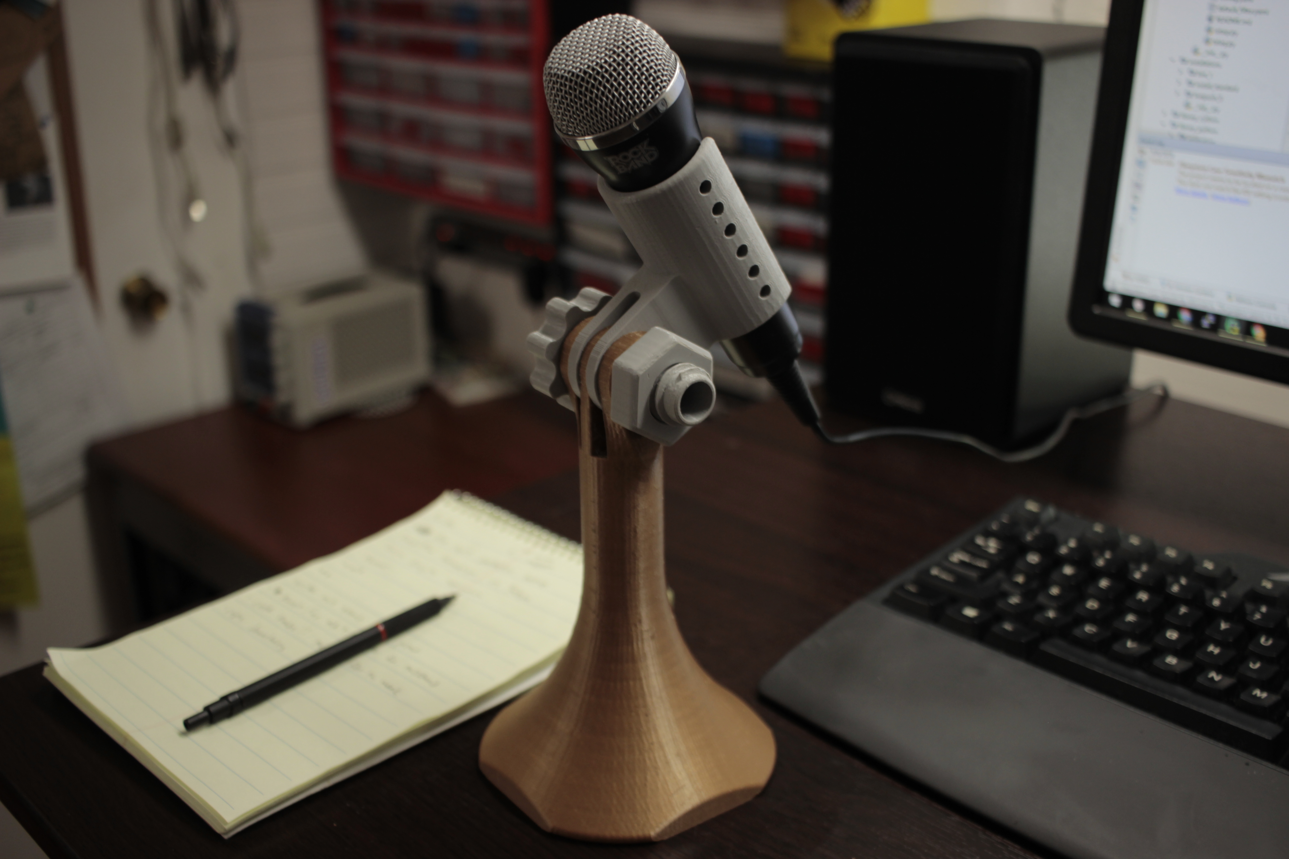
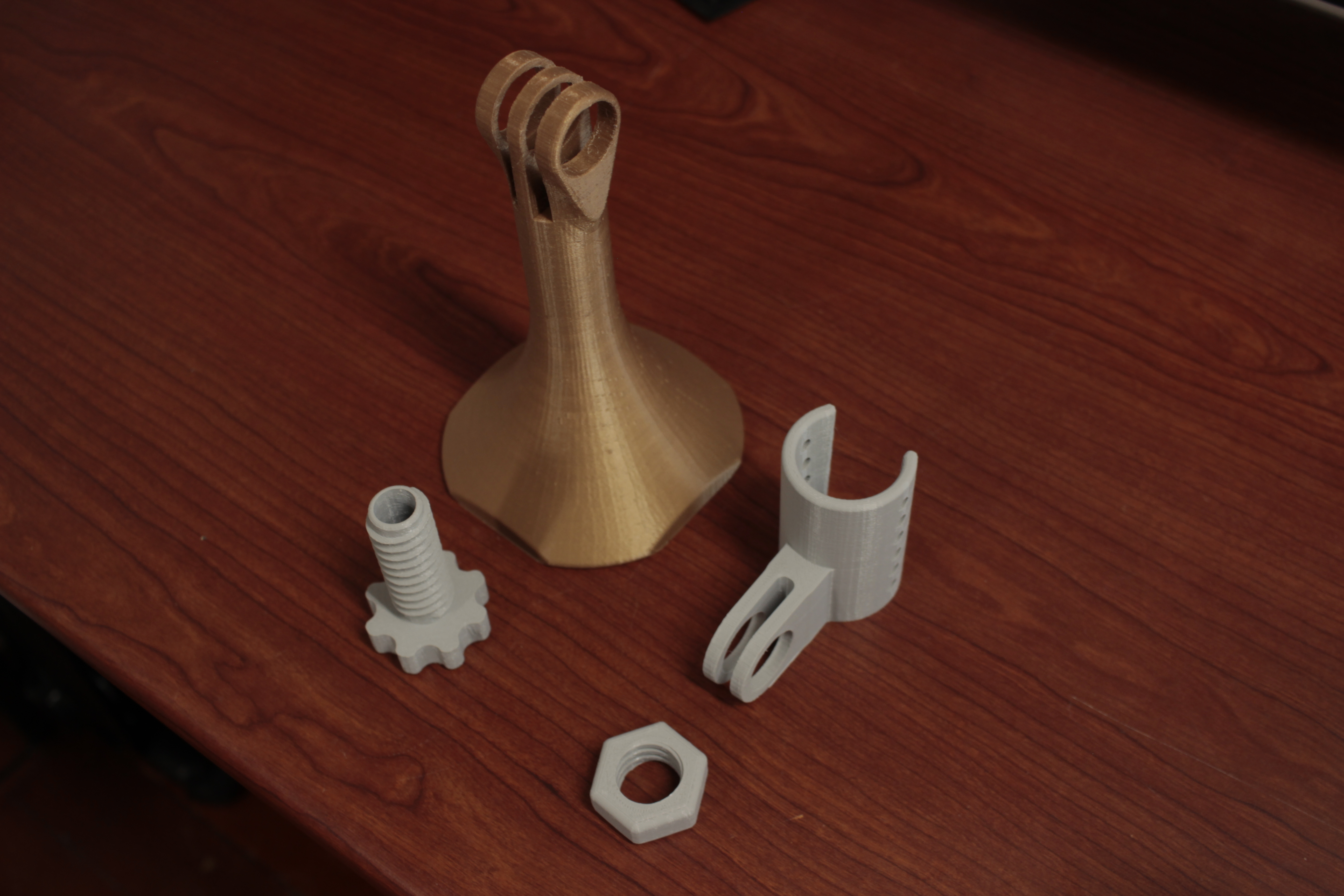
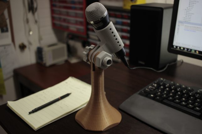
This is a quick design I came up with rather than spend the $20 on amazon. You can get the STL files on thingiverse here.
Here’s a video:
Here are some images:
This is a quick design I came up with rather than spend the $20 on amazon. You can get the STL files on thingiverse here.

This project got featured on the official arduino blog as well as hackaday! Thanks to everyone that shared!
I work with addressable LEDs a lot. For all that they’re great for, they’re kind of hard to debug when you have a lot of them connected up at once. This is especially apparent when you have many small single modules in hard to reach spaces.
Here’s my solution:
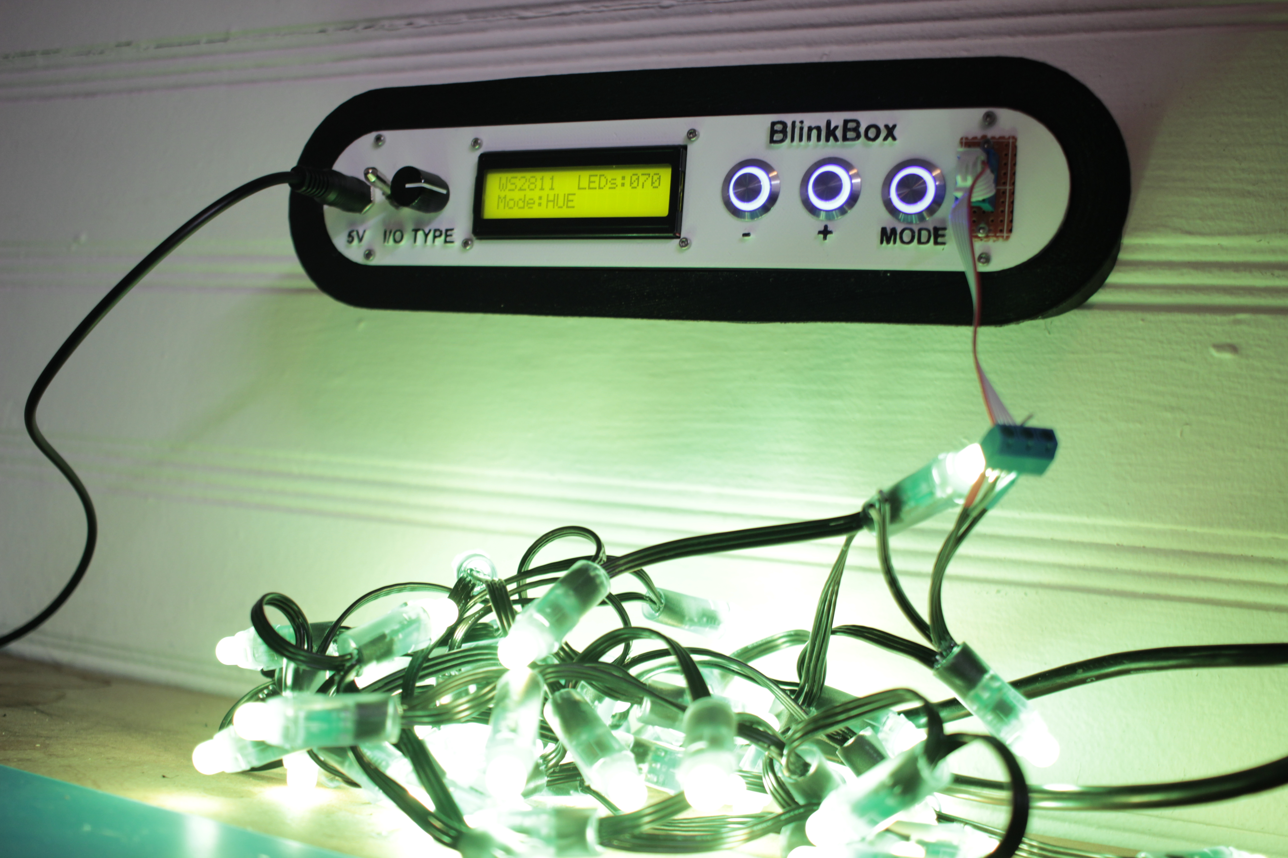
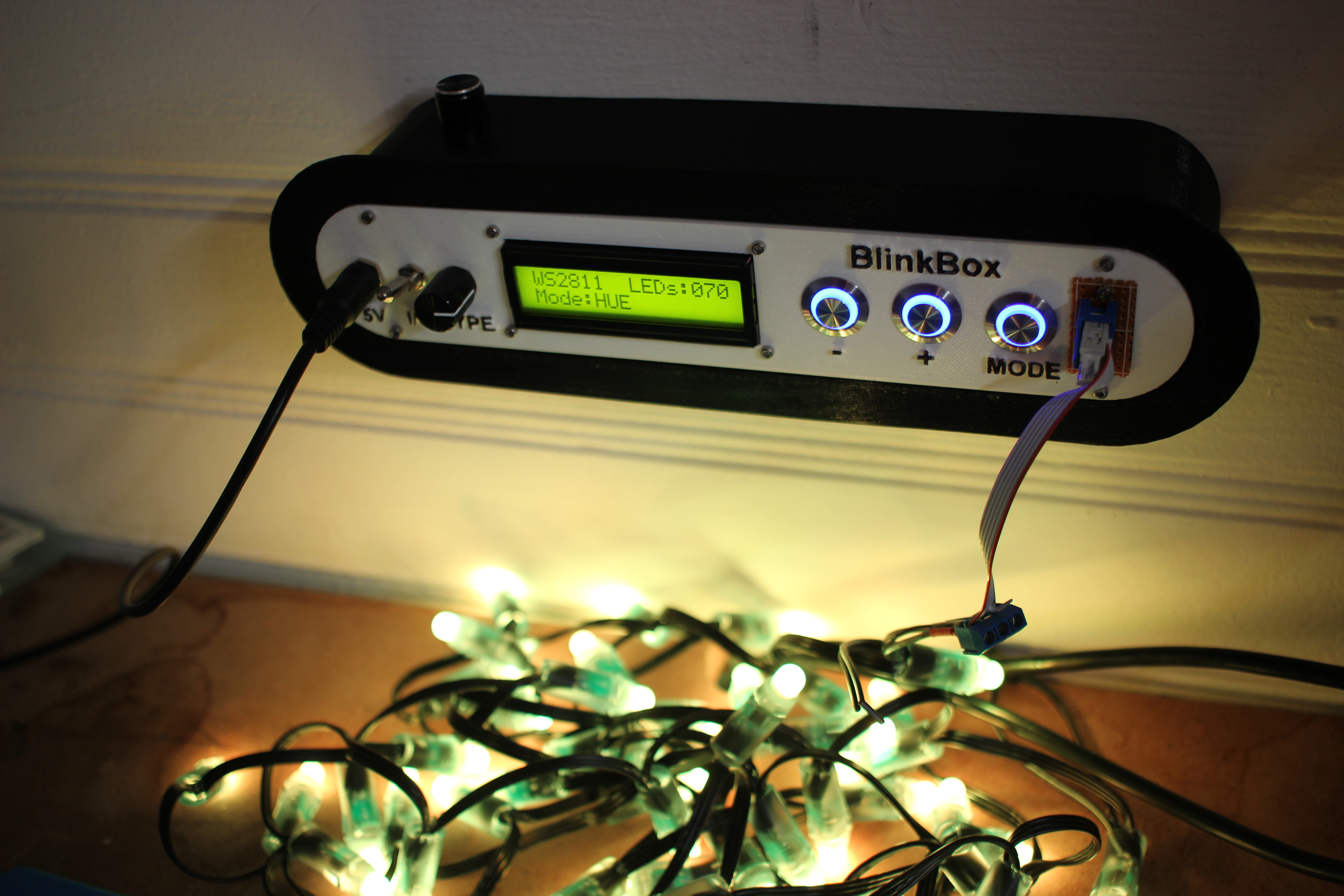
This lets me set the color and number of LEDs in a strip, and then displays a color pattern. This way I can tell if an LED has become disconnected in a strip, or if a channel inside a particular has died.
HSV (x, 255, 255) and x loops from 0-255RGB(255, 255, 255)All of the raw code solidworks, and KiCAD have been posted on my github. You can look at the 3D models on thingiverse as well.
Here are a couple of quick renders of the assembly design:
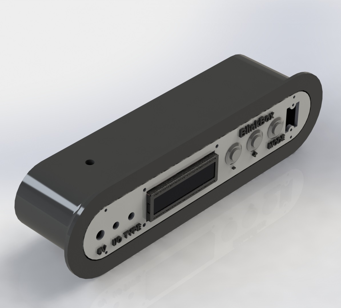
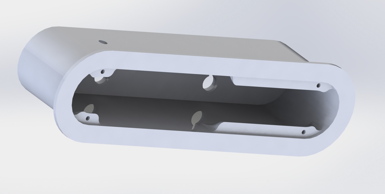
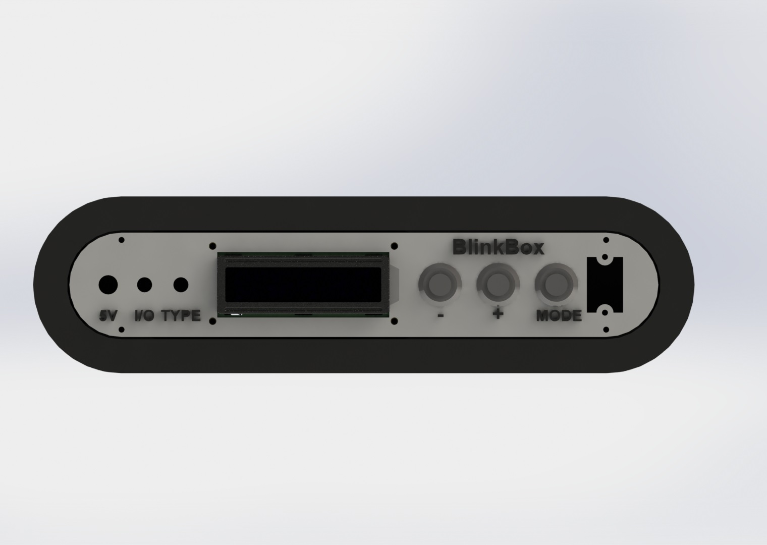 The screw mount behind the pushbuttons is extended to be able to support the pressure without flexing:
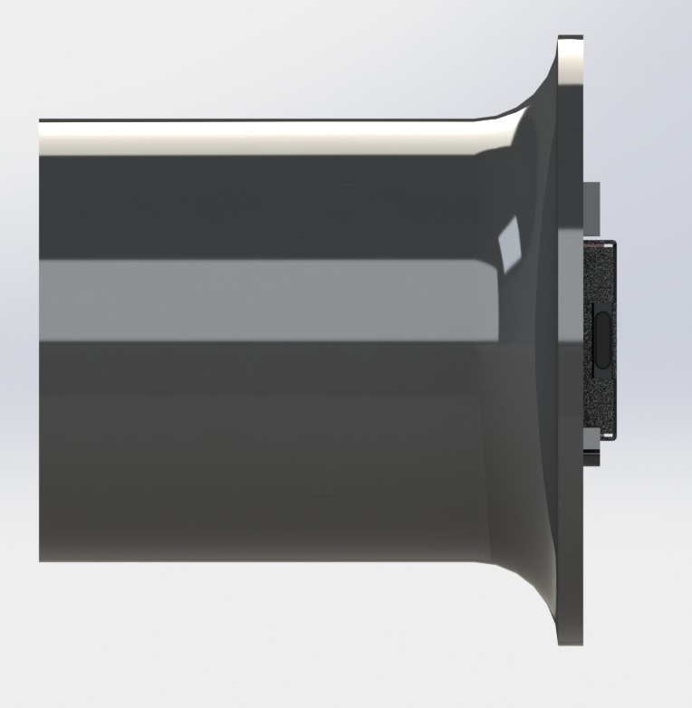
 I added a ridge so you can grab onto something as you interact with the switches / buttons.
Here’s the circuit:
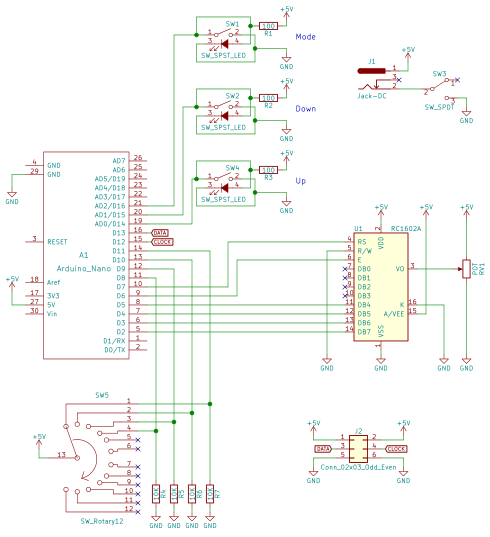
There really isn’t a lot going on here, the parts are probably the coolest part of the project. The 5V jack is a 6mm DC barrel jack, the pushbuttons are illuminated 16mm pushbuttons from adafruit, the on/off switch is a locking toggle switch, and the 4 position rotary switch can be found here.
I wired up the circuit on a spare piece of perfboard.
My code is available on my github.
The LED driving part of the code is based on FastLED, a beautiful library for driving these types of addressable LEDs.
The rest of the code is mostly just a hardware UI problem, and isn’t all that interesting. LED count “ramps” as you hold the button down. The longer you hold the button, the faster the
That’s pretty much it! I’ve already gotten some use out of this tool and have found great satisfaction in taking the time to make it look nice as it will be a permanent addition to my lab.
I’ll post any updates I make to this project as edits to the top of this post.
Thanks for reading, and here are a few more photos:
It’s well known that nylon based 3D printer filaments need to be dried out before they’re used. What happens though when you have a 30+ hour print? The spool can take on a lot of moisture in that amount of time and compromise the print.
Many people have solved this problem by making filament dryboxes, somewhat airtight containers that contain a desiccant to dry out the air inside of the chamber.
I have to print several large parts from nylon for client, and I was having trouble in the last hours of the print due to the spool taking on water from the air. I decided to build one of these chambers but with a twist:
Mine is wall mounted! Space in my lab is a premium and the walls are free real estate.
The parts for this build is are available on my Thingiverse page. Oh and if you’re curious, I’m using a wall-outlet-rechargeable desiccant pack from Amazon which I got for $15.
The bolts are M3x10mm, and the nuts are M3 nuts, both from McMaster Carr.
Thanks for reading!
Python uses a Global Interpreter Lock to make sure that memory shared between threads isn’t corrupted. This is a design choice of the language that has it’s pros and cons. One of these cons is that in multi-threaded applications where at least one thread applies a large load to the CPU, all other threads will slow down as well.
For multi-threaded Python applications that are at least somewhat time-sensitive, you should use Processes over Threads.
I wrote a simple python script to show this phenomenon. Let’s take a look.
|
1 2 3 4 5 6 7 |
def increment(running_flag, count_value): c = 0 while True: if not running_flag.value: break count_value.value = c # setting a Value is atomic c += 1 |
The core is this increment function. It takes in a Value and then sets it over and over, increment each loop, until the running_flag is set to false. The value of count_value is what is graphed later on, and is the measure of how fast things are going.
The other important bit is the load function:
|
1 2 3 4 5 6 |
def load(running_flag): z = 10 while True: if not running_flag.value: break z = z * z |
Like increment, load is the target of a thread or process. The z variable quickly becomes large and computing the loop becomes difficult quickly.
The rest of the code is just a way to have different combinations of increment and load running at the same time for varying amounts of time.

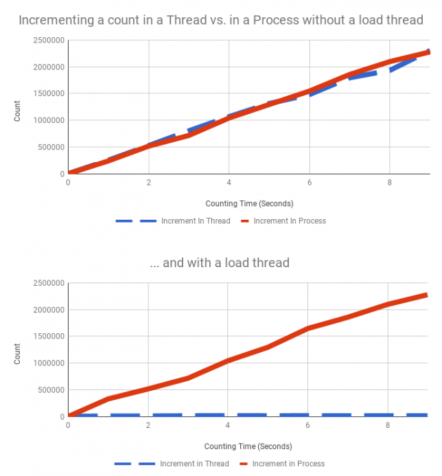
The graph really tells the story. Without the load thread running, the process and thread versions of increment run at essentially the same rate. When the load thread is running, increment in a thread grinds to a halt compared to the process which is unaffected.
That’s all! I’ve pasted the full source below so you can try the experiment yourself.
|
1 2 3 4 5 6 7 8 9 10 11 12 13 14 15 16 17 18 19 20 21 22 23 24 25 26 27 28 29 30 31 32 33 34 35 36 37 38 39 40 41 42 43 44 45 46 47 48 49 50 51 52 53 54 55 56 57 58 59 60 61 62 63 64 65 66 67 68 69 70 71 72 73 74 75 76 77 78 79 80 81 82 83 84 85 86 87 88 89 90 91 92 93 94 95 96 97 98 99 |
from multiprocessing import Process, Value from threading import Thread from time import sleep from ctypes import c_bool, c_longdouble def increment(running_flag, count_value): """ Increment the value in count_value as quickly as possible. If running_flag is set to false, break out of the loop :param running_flag: a multiprocessing.Value boolean :param count_value: a multiprocessing.Value Long Double """ c = 0 while True: if not running_flag.value: break count_value.value = c # setting a Value is atomic c += 1 def load(running_flag): """ Apply a load to the CPU. If running_flag is set to false, break out of the loop :param running_flag: a multiprocessing.Value boolean """ z = 10 while True: if not running_flag.value: break z = z * z def mct(target, flag, value): """ Returns a lambda that can be called to get a thread to increment a increment using a thread """ return lambda: Thread(target=target, args=(flag, value)) def mcp(target, flag, value): """ Returns a lambda that can be called to get a thread to increment a increment using a process """ return lambda: Process(target=target, args=(flag, value)) def mlt(target, flag): """ Returns a lambda that can be called to get a thread that will load down the CPU """ return lambda: Thread(target=target, args=(flag,)) if __name__ == "__main__": f = Value(c_bool, True) # control flag, will be passed into child thread/process so they can be stopped cv = Value(c_longdouble, 0) # increment value child_lists = [mct(increment, f, cv)], [mcp(increment, f, cv)], [mct(increment, f, cv), mlt(load, f)], [mcp(increment, f, cv), mlt(load, f)] for delay in range(10): # maximum run time of 10 seconds max_counts = [] for get_children in child_lists: # reset the flag and increment f.value = True cv.value = 0 # the child thread/processes will end up in here children = [] for get_child in get_children: child = get_child() # create a new instance of the thread/process to be launched child.start() children.append(child) sleep(delay) f.value = False for child in children: child.join() # stop the process max_counts.append(cv.value) s = "" for count in max_counts: s += str(count) + " " print(s) |
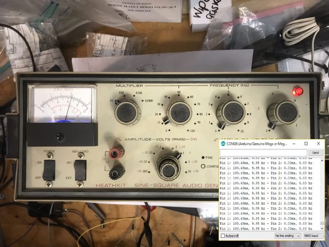
Ever wanted to measure the frequency of a square wave using an Arduino? There are a couple of good solutions out of there to do this, but not all of them had the capacity to do multiple inputs. I couldn’t find this quickly so here is my solution.
Here’s the link to the code if you want to skip ahead. The code uses interrupts and doesn’t use any kind of delaying so it’s good for giant state-machine applications. My application for this is measuring signals from 10Hz-100Hz in which this can measure within 1% error. The absolute limits of the code are 1Hz-50KHz.
This project is on GitHub if you want to send a pull request to make improvements.
For testing, I wrote a simple function generator and uploaded it to a separate arduino. It outputs a pulse train with periods of 10ms (100Hz) and 5ms (200Hz) on pins 2 and 3. I attached LEDs and their resistors for debugging.
Pins 2 and 3 on the function generator to pins 2 and 3 on the frequency counter.
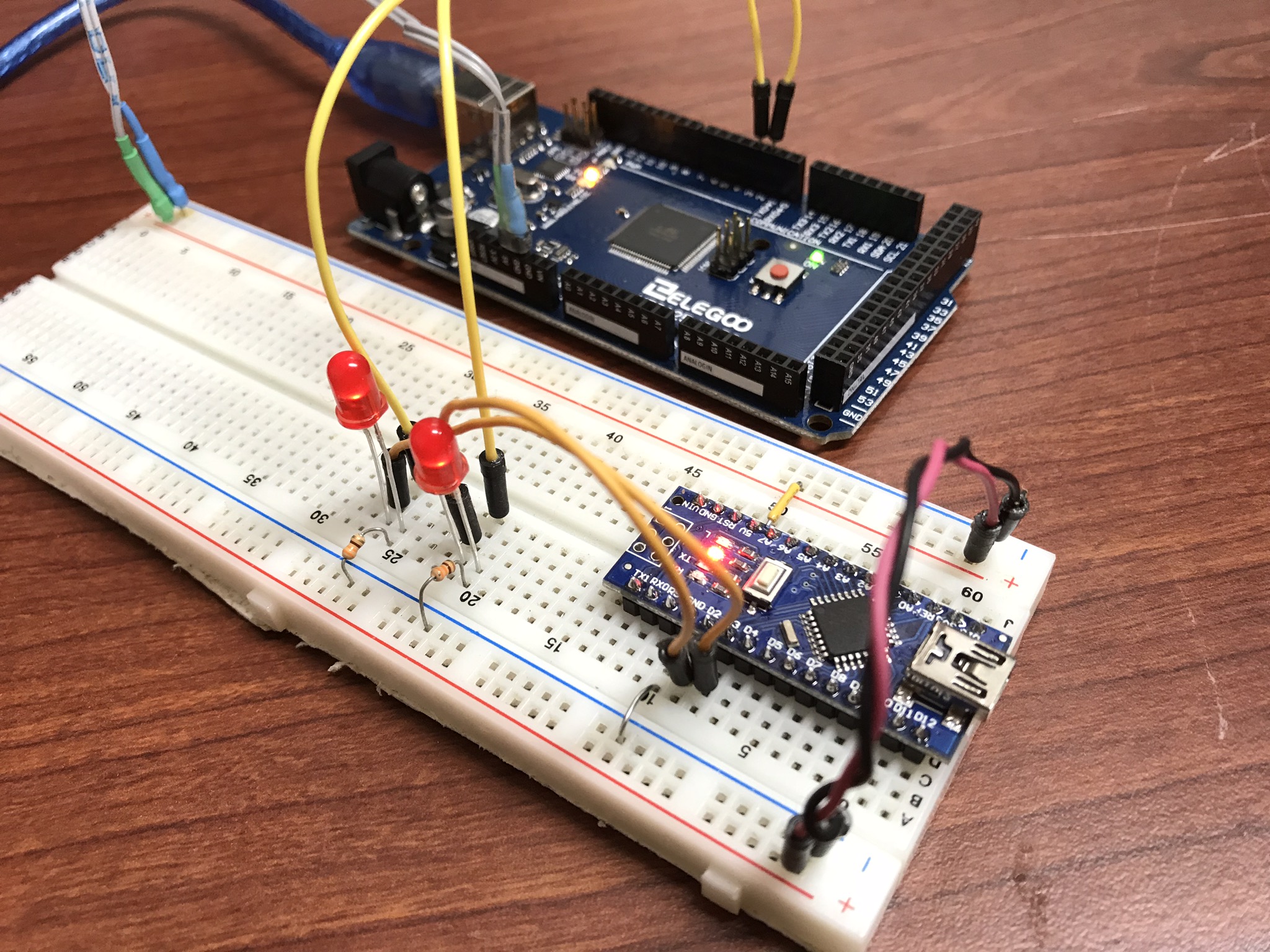
The code for this simple function generator is here:
|
1 2 3 4 5 6 7 8 9 10 11 12 13 14 15 16 17 18 19 20 21 22 23 24 25 26 27 28 29 30 31 32 33 34 35 |
/* * 3/29/2018 - Devon Bray - https://www.esologic.commultiple-frequency-counter-arduino/ */ int pin_100Hz = 2; int pin_200Hz = 3; unsigned long previous_time_100Hz; unsigned long previous_time_200Hz; void setup() { pinMode(pin_100Hz, OUTPUT); pinMode(pin_200Hz, OUTPUT); } void loop() { unsigned long current_time = millis(); if ( (current_time - previous_time_200Hz) >= 5) { digitalWrite(pin_200Hz, HIGH); delayMicroseconds(1000); digitalWrite(pin_200Hz, LOW); previous_time_200Hz = current_time; } if ( (current_time - previous_time_100Hz) >= 10) { digitalWrite(pin_100Hz, HIGH); delayMicroseconds(1000); digitalWrite(pin_100Hz, LOW); previous_time_100Hz = current_time; } } |
This code will work fine in a stateless application, because there are no delay statements (which some other frequency counters I’ve seen online use). It’s a little bit complicated, send me a pull request if you can refactor it to be cleaner.
Here’s the sketch:
|
1 2 3 4 5 6 7 8 9 10 11 12 13 14 15 16 17 18 19 20 21 22 23 24 25 26 27 28 29 30 31 32 33 34 35 36 37 38 39 40 41 42 43 44 45 46 47 48 49 50 51 52 53 54 55 56 57 58 59 60 61 62 63 64 65 66 67 68 69 70 71 72 73 74 75 76 77 78 79 80 81 82 83 84 85 86 87 88 89 90 91 92 93 94 95 96 97 98 99 100 101 102 103 104 105 106 107 108 109 110 111 112 113 114 115 116 117 118 119 120 121 122 |
/* * 3/29/2018 - Devon Bray - https://www.esologic.commultiple-frequency-counter-arduino/ * * I've written most of the important notes as comments in the source, but a couple more details: * * - The important data is stored in `period_averages_ms` and `frequency_averages_hz`. You address them using the indices defined at the top of the file. These arrays get updated each time `compute_counts()` is called. Keep it `compute_counts()` somewhere in the main() loop. * * - You could easily add more frequencies, you just have to `NUMSIGS`, make a specific ISR, and another `attachInterrupt` line in setup() * * - It uses [interrupts](https://playground.arduino.cc/Code/Interrupts) which might not be right for your proejct, but normally shouldn't get in the way of too much stuff. * * - If the ISR hasn't seen a new edge in 1000000us, both `period_averages_ms[p_index]` and `frequency_averages_hz[p_index]` will be set to zero! * - This means that slowest frequency that this code can detect is 1hz! * */ int freq_pin_1 = 2; // the pin connected to the first signal, must be an interrupt pin! See the arduino docs int freq_pin_2 = 3; // the pin connected to the second signal, must be an interrupt pin! See the arduino docs #define BUFFSIZE 100 // a rolling average of the frequency/period is computed, and this is the size of that buffer #define NUMSIGS 2 #define FREQ1INDEX 0 #define FREQ2INDEX 1 volatile int period_buffer_indices[NUMSIGS] = { 0 }; // the location of the index for adding to the rolling buffer average volatile unsigned long period_buffers[NUMSIGS][BUFFSIZE] = { 0 }; // the buffers volatile unsigned long previous_edge_times_us[NUMSIGS] = { 0 }; // the time that the previous edge came in in microseconds volatile float period_averages_ms[NUMSIGS] = { 0 }; // the period time of a given signal in milliseconds volatile float frequency_averages_hz[NUMSIGS] = { 0 }; // the frequency of a given signal in hertz volatile bool period_buffer_locked[NUMSIGS] = { false }; // spin locks for the different buffers void setup() { Serial.begin(9600); // the pins must be mapped to their ISRs pinMode(freq_pin_1, INPUT_PULLUP); attachInterrupt(digitalPinToInterrupt(freq_pin_1), new_freq1_edge, RISING); // you could change this mode to whatever you were looking for, FALLING, CHANGE etc. pinMode(freq_pin_2, INPUT_PULLUP); attachInterrupt(digitalPinToInterrupt(freq_pin_2), new_freq2_edge, RISING); } void loop() { compute_counts(); Serial.print("Pin 1: "); Serial.print(period_averages_ms[FREQ1INDEX]); Serial.print("ms, "); Serial.print(frequency_averages_hz[FREQ1INDEX]); Serial.print(" hz"); Serial.print(" - Pin 2: "); Serial.print(period_averages_ms[FREQ2INDEX]); Serial.print("ms, "); Serial.print(frequency_averages_hz[FREQ2INDEX]); Serial.print(" hz"); Serial.println(""); } void compute_counts() { // computes the average of the buffer for a given signal. Must be called before using the period_averages_ms or frequency_averages_hz buffers. for (int p_index = 0; p_index < NUMSIGS; p_index++) { float buffer_sum = 0; while (period_buffer_locked[p_index]) {}; // wait around for the ISR to finish period_buffer_locked[p_index] = true; // ISR won't add new data to `period_buffers` if ((micros() - previous_edge_times_us[p_index]) < 1000000) { for (int j = 0; j < BUFFSIZE; j++) { buffer_sum += period_buffers[p_index][j]; } } period_buffer_locked[p_index] = false; // ISR will now add new data to `period_buffers` if (buffer_sum > 0){ period_averages_ms[p_index] = ((buffer_sum / (float)BUFFSIZE)) / 1000; frequency_averages_hz[p_index] = (1 / period_averages_ms[p_index]) * 1000; } else { period_averages_ms[p_index] = 0; frequency_averages_hz[p_index] = 0; } } } void new_edge(int period_index) { unsigned long current = micros(); if (period_buffer_locked[period_index] == false) { // if compute_counts is using the buffer, skip adding to it because that process isn't atomic period_buffer_locked[period_index] = true; period_buffers[period_index][period_buffer_indices[period_index]] = current - previous_edge_times_us[period_index]; period_buffer_locked[period_index] = false; period_buffer_indices[period_index]++; if (period_buffer_indices[period_index] >= BUFFSIZE) { period_buffer_indices[period_index] = 0; } } previous_edge_times_us[period_index] = current; // but make sure the new time is set because this operation is atomic } void new_freq1_edge() { new_edge(FREQ1INDEX); } void new_freq2_edge() { new_edge(FREQ2INDEX); } |
I’ve written most of the important notes as comments in the source, but a couple more details:
period_averages_ms and frequency_averages_hz. You address them using the indices defined at the top of the file. Make sure you call compute_counts() before using this data. Keep it somewhere in main().NUMSIGS, make a specific ISR, and another attachInterrupt line in setup()period_averages_ms[p_index] and frequency_averages_hz[p_index] will be set to zero! This means that slowest frequency that this code can detect is 1Hz!If you have any questions on how to add more signals, leave a comment!
Here’s the output in the serial monitor attached to my function generator from earlier:
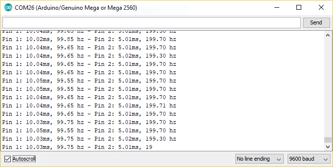
That’s like less than 1% error! Pretty good!
I also tested the code with a real function generator. Things worked really well until around 50KHz, so I would say that this code can’t be trusted past 50KHz.
10 Hz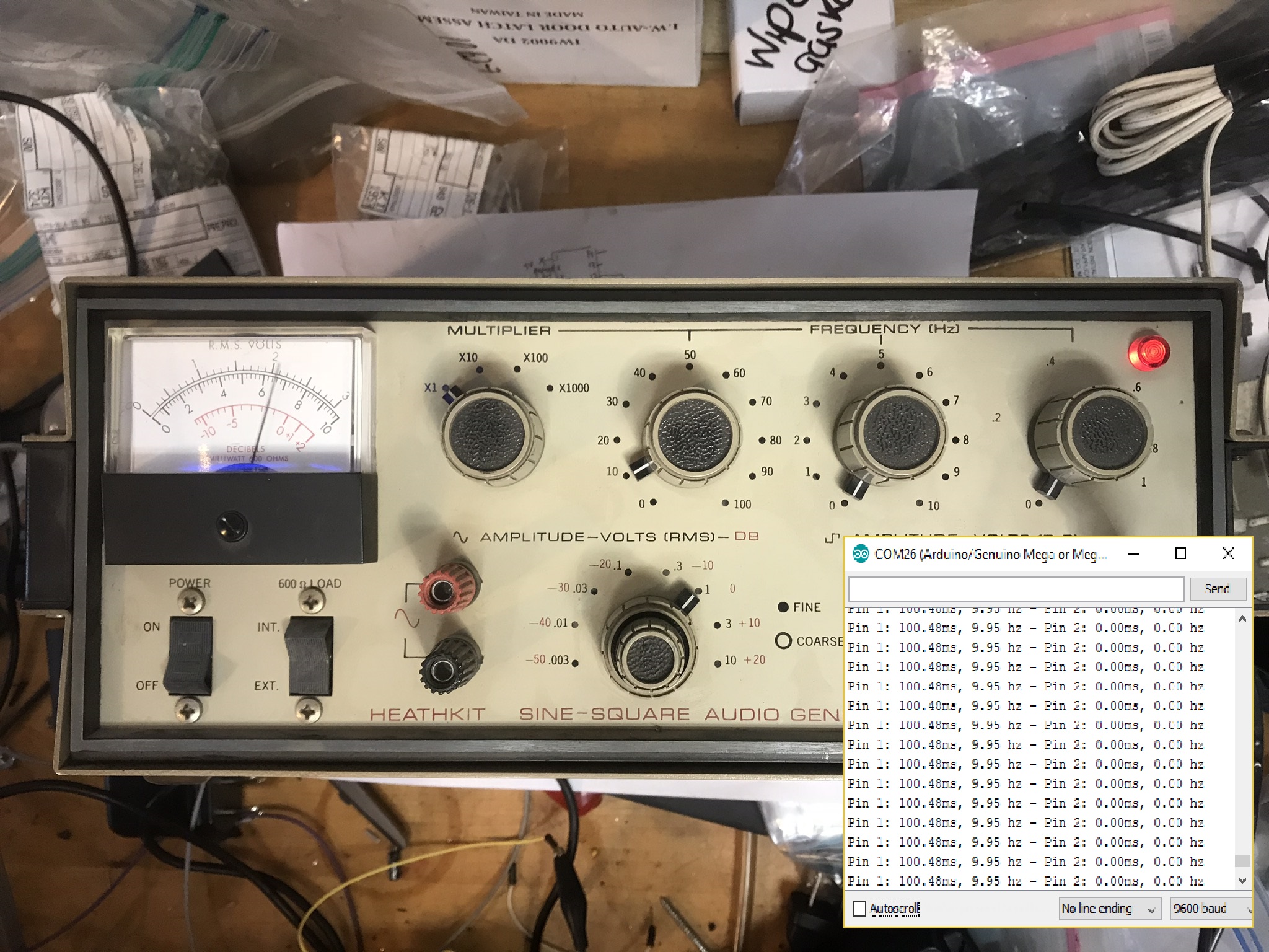
50 KHz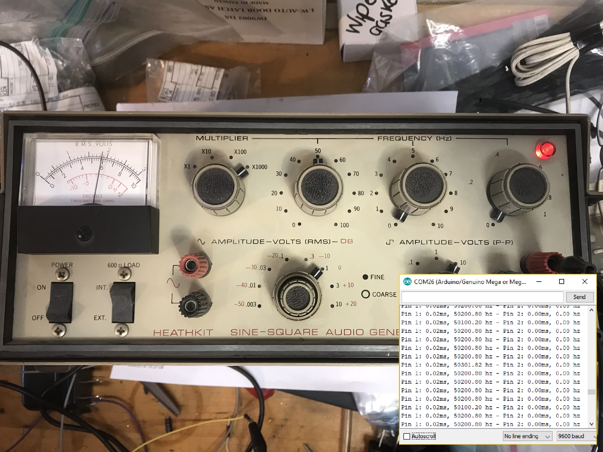
Thanks for reading!
Here’s a video:
#goodprints – ep1💥 @Raspberry_Pi shelf mount, Wallet & Keys holder & spool hook #3Dprinting https://t.co/VJzBA0fKx3 https://t.co/zwzWACuzzE
— Devon Bray (@eso_logic) November 6, 2017
For a while I’ve been logging my favorite prints here but some of them are two small to warrant a post. So introducing: #goodprints! At first I’m going to shoot for monthly installments, but as I print more, I’ll post more.
This time we’ve got 3 prints in the above video. Here are the details:
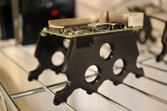
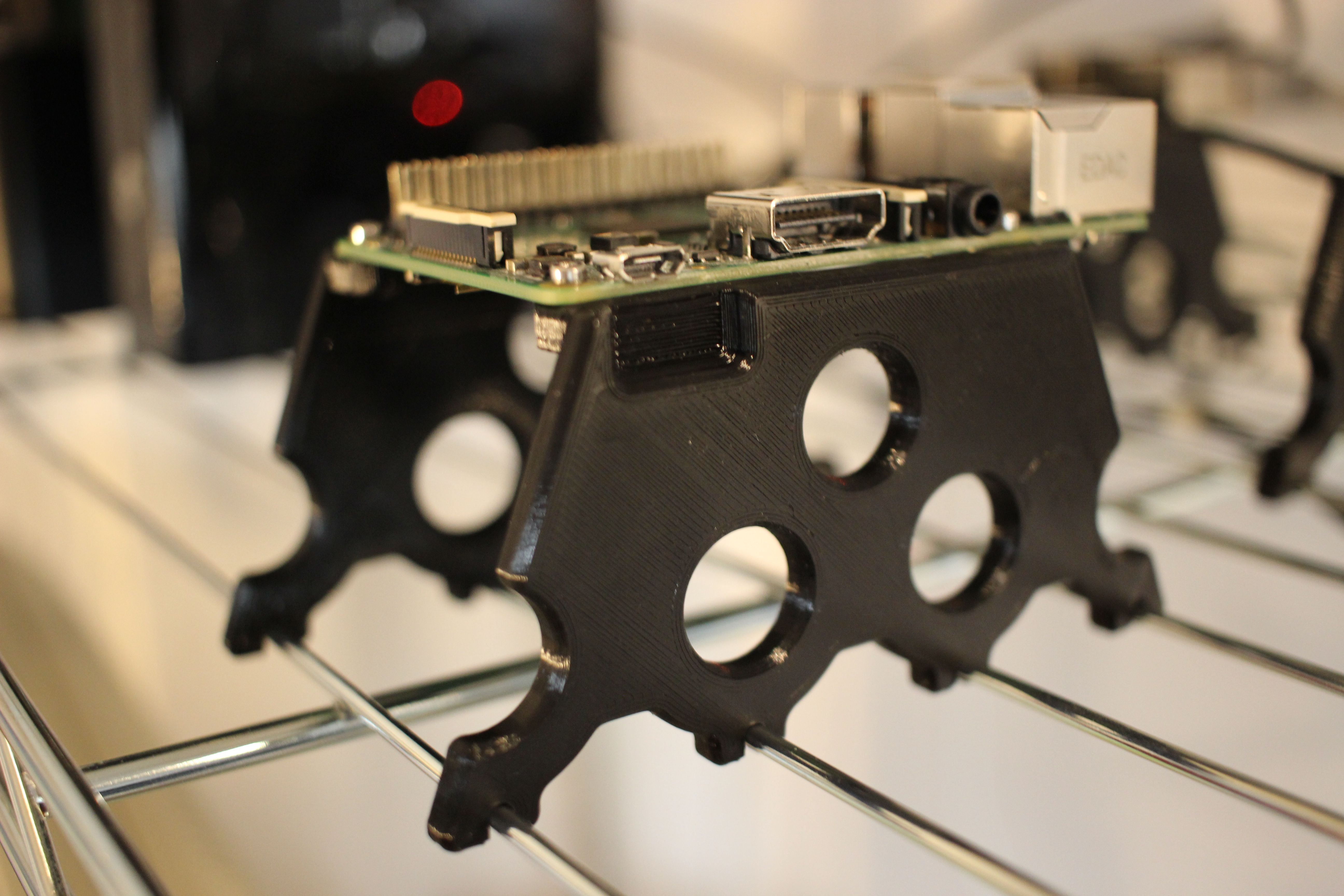
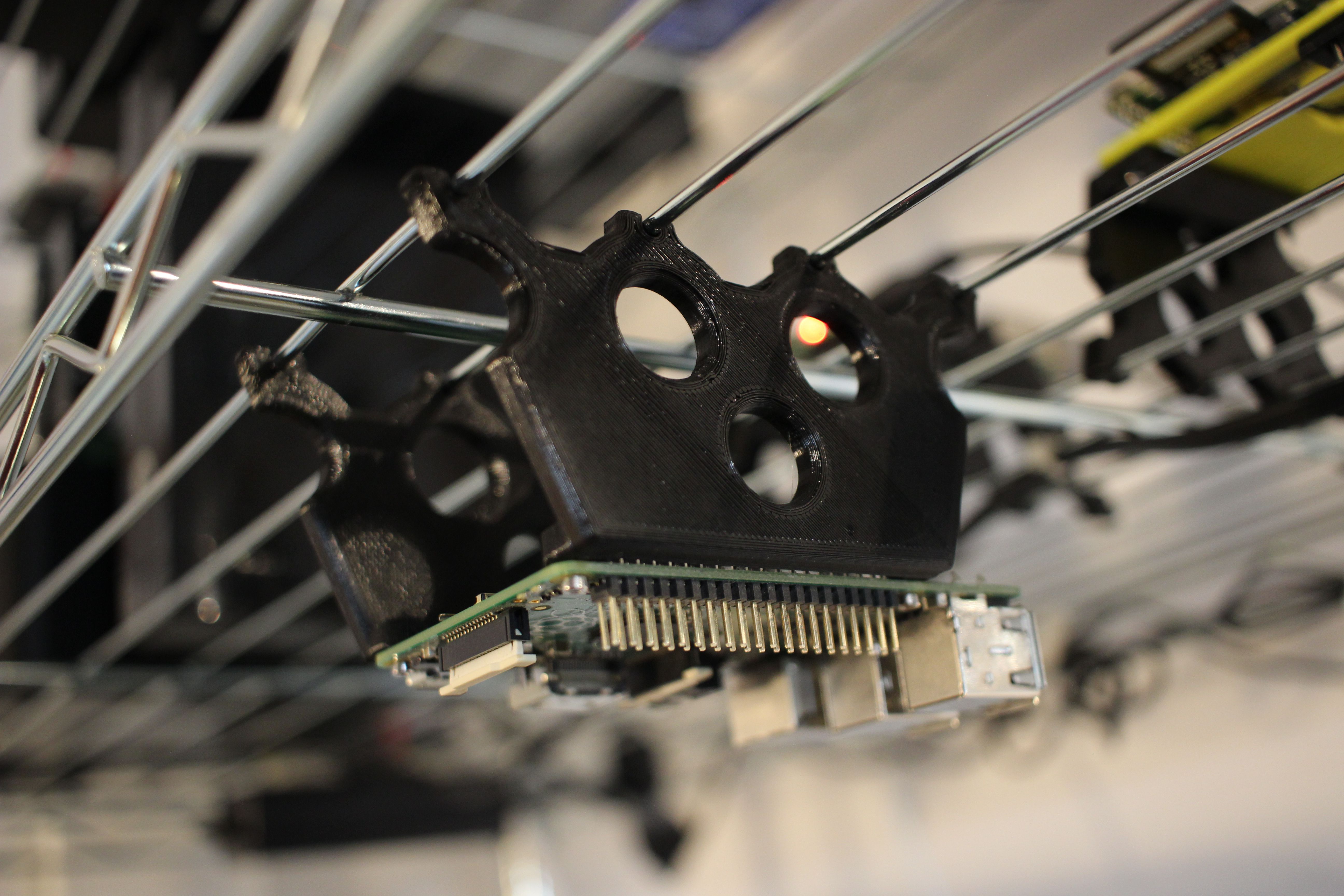
Raspberry Pi Wire Shelf Mount – Everyone knows that wire shelves are the best. Now you can securely mount a Raspberry Pi to one. Thingiverse Link
 Here is the drawing for mating with the shelf: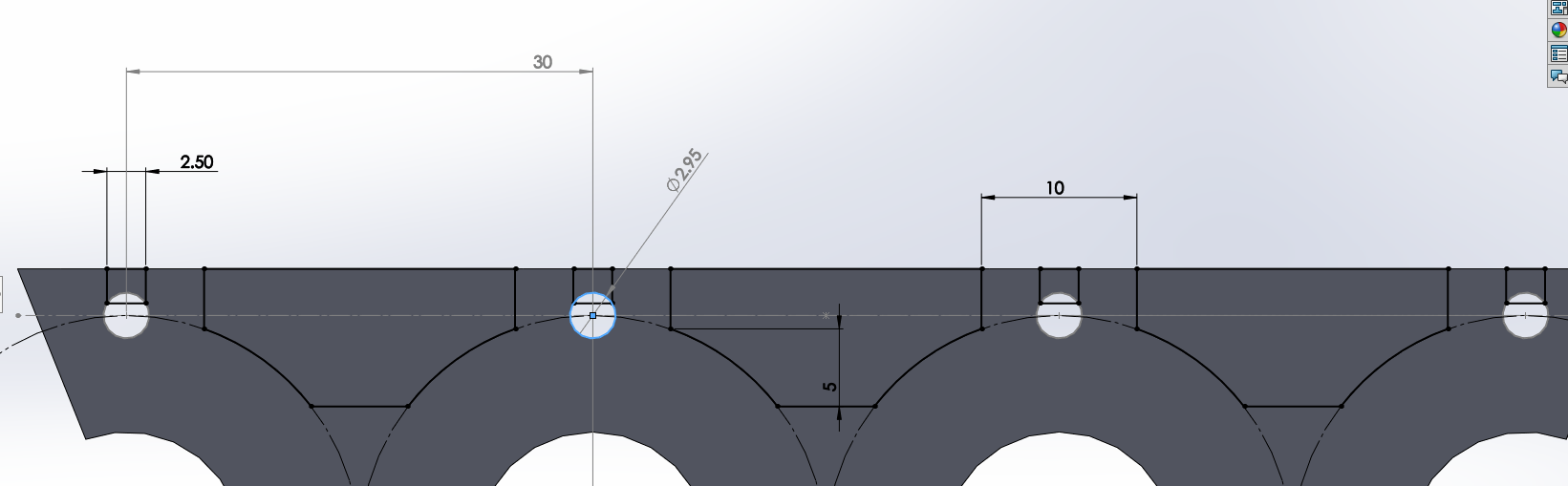
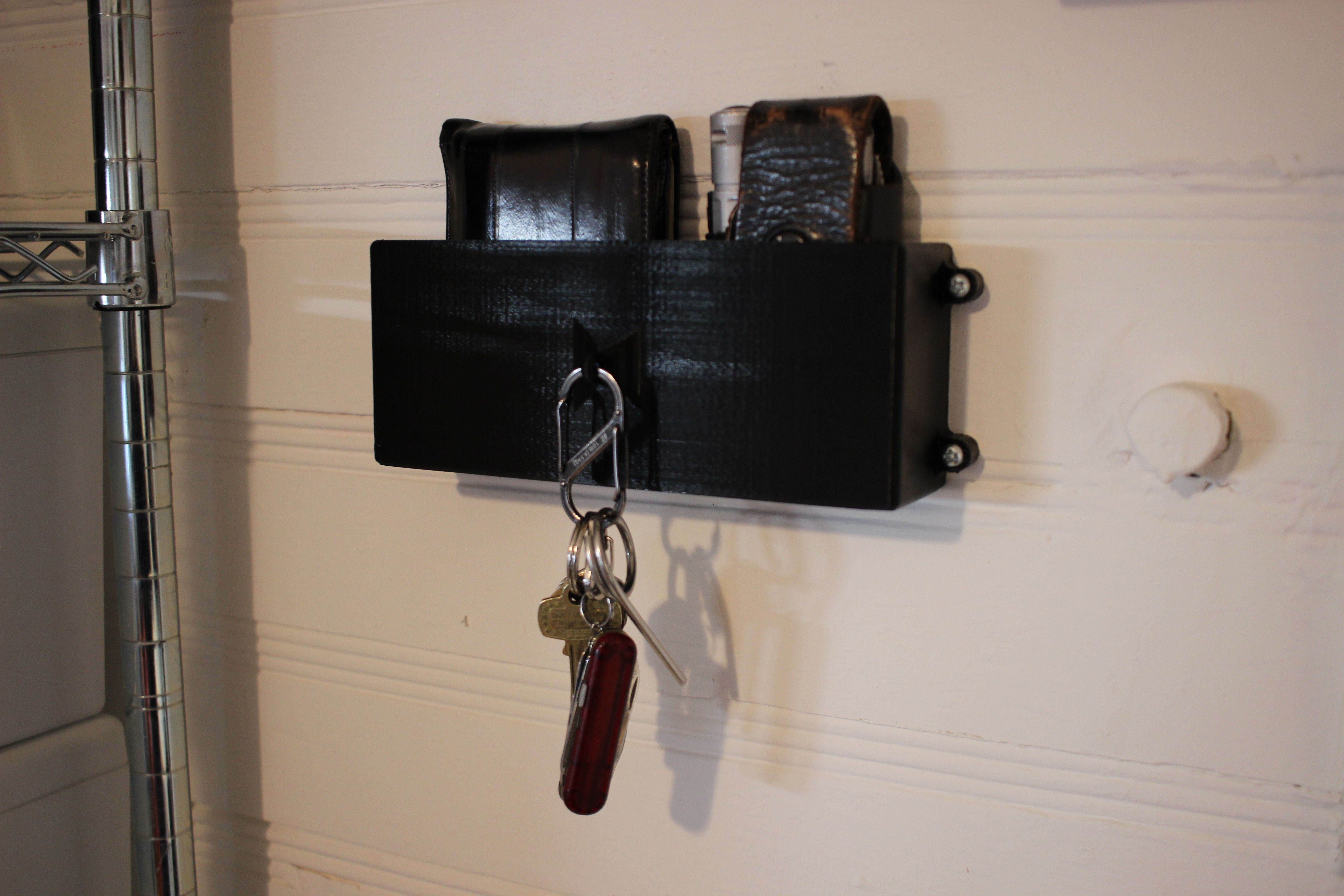
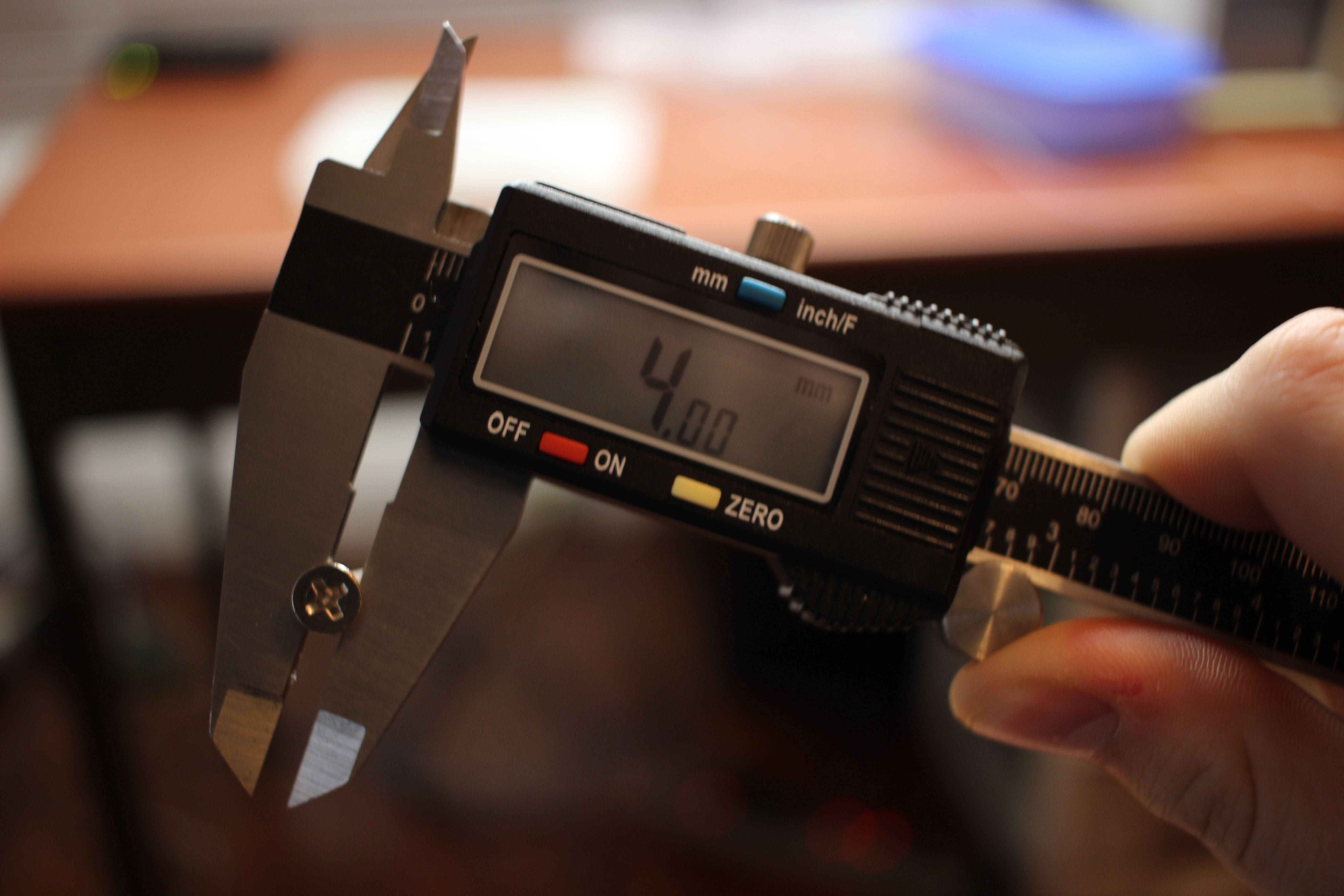
Wallet, Keys & Leatherman Wall Mount – I’m constantly loosing these things in my lab, now they’re not going anywhere. Thingiverse Link
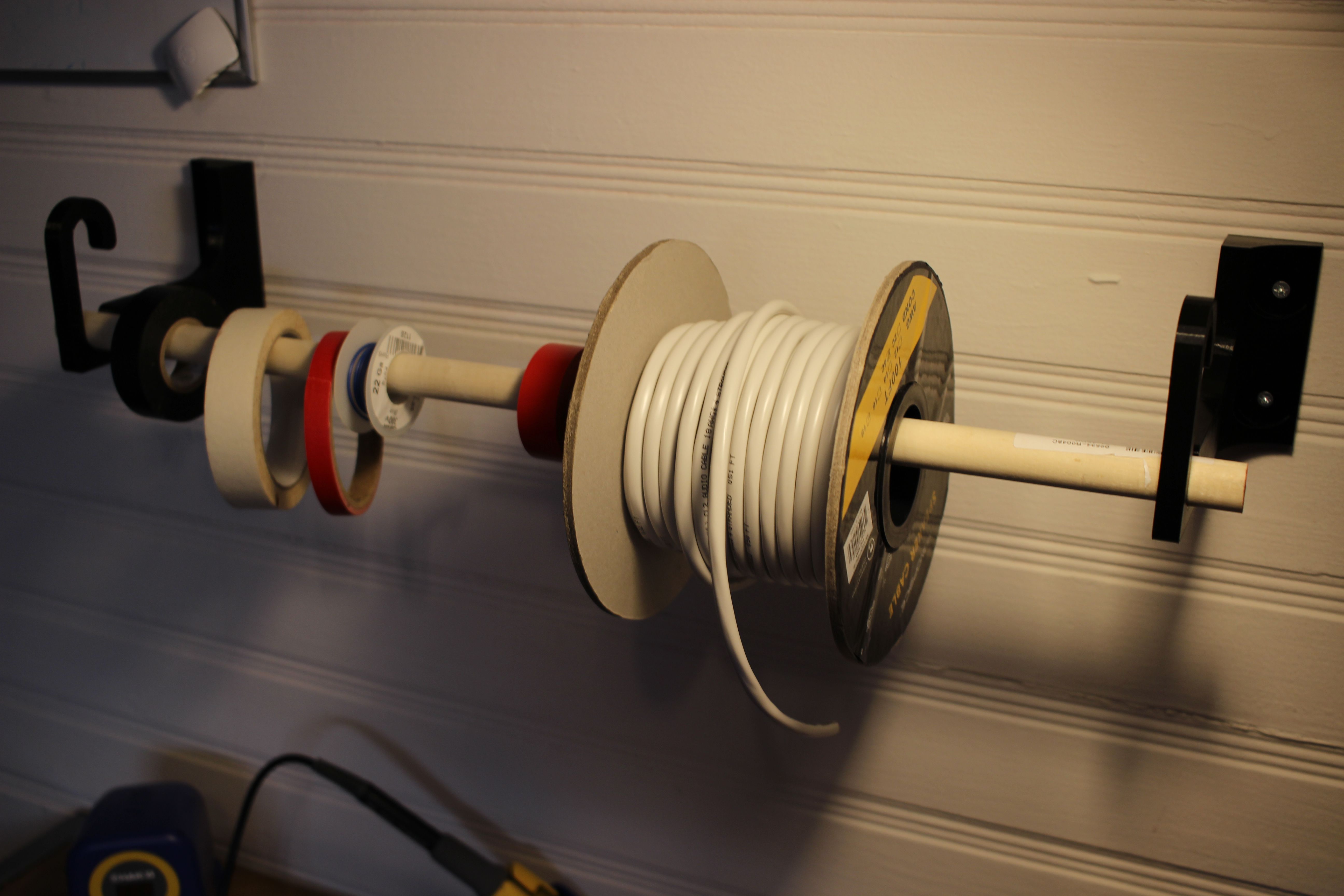
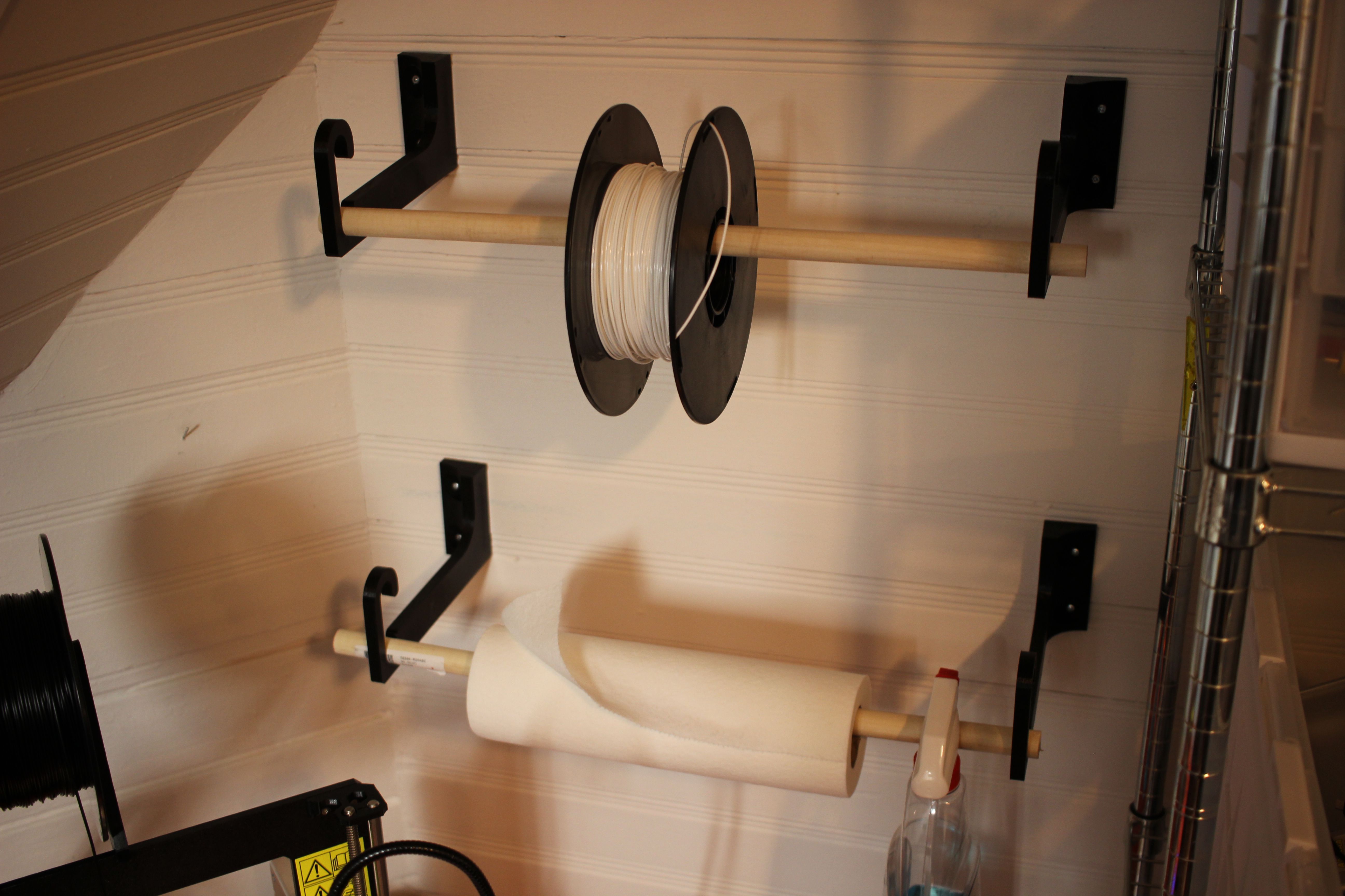
Wall Hook – This is for mounting stuff like filament spools, wire, and tape to the wall. It accepts 3/4 inch dowels. There are two version, one 85mm long and one 150mm long (designed to fit hatchbox 1kg filament spools). Thingiverse Link
I figured that doing this would be trivial but turns out it took a little work:
I’m trying to emulate an official 7″ Raspberry Pi Touch Display in a VM, so for this post the target resolution is 800 x 480. If you want to change it to another resolution swap in yours for the rest of this guide.
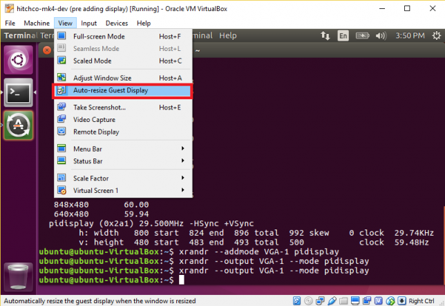
First, make sure Auto-resize Guest Display is deselected in Virtualbox:
Run the following command in your terminal:
|
1 |
cvt 800 480 60 |
The output should look something the the following, starting with Modeline…
Copy the text after Modeline so in this case it would be
|
1 |
"800x480_60.00" 29.50 800 824 896 992 480 483 493 500 -hsync +vsync |
And paste it after the following command:
|
1 |
xrandr --newmode |
NOTE! You may want to change the 800x480_60.00 to something without an underscore in it, it was causing problems on my system. I changed it to pidisplay. The resulting command for this example is:
|
1 |
xrandr --newmode "pidisplay" 29.50 800 824 896 992 480 483 493 500 -hsync +vsync |
You should be able to run the above command without error. Next, run:
|
1 |
xrandr -q |
You’ll be greeted with output similar to this. Note the name of the display device, in this case VGA-1.
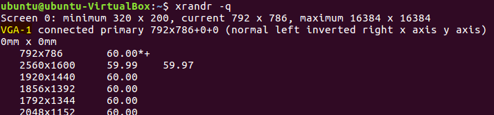 With that output name, enter the following two commands:
|
1 2 |
xrandr --addmode VGA-1 pidisplay xrandr --output VGA-1 --mode pidisplay |
After running that second command, the window should jump to it’s new resolution! You’re done!

This time we’re trying to work through a hardware bug!
Without warning, my printer would stop it’s current print and display “THERMAL RUNAWAY” on the display screen:
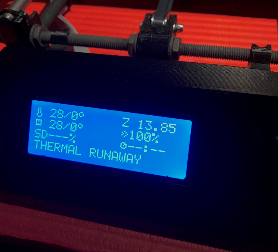
This would happen once every couple of prints or so.
According Prusa’s Docs a common cause of this is problems with the thermistor connection. They show a graph that has very erratic readings from the sensor:
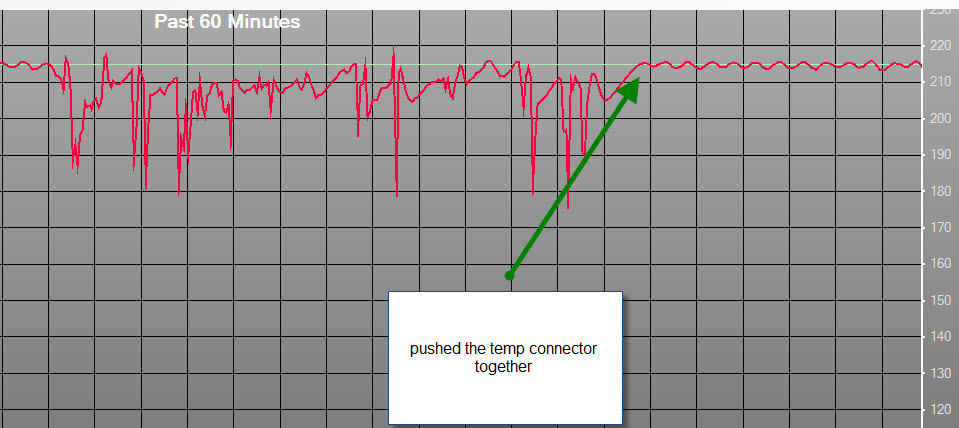 This seemed like a good place to start so I re-seated the connector and used octoprint to generate my own graph:
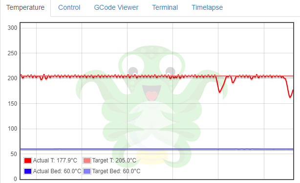
No erratic readings, the temp would drop off and then start heating back up.
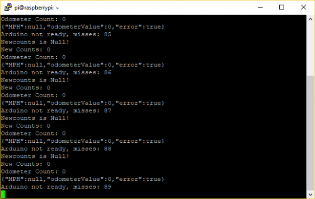
The problem ended up being the connection between the terminal lug and the wire on the heater in the hotend. To fix this, I cut off the crimp lug and stripped away some insulation. I put this into the screw terminal block. I’ve done a couple of prints and had no issues after making this modification.
Here is a quick way to have an application built on electron run at boot on a Raspberry Pi. This worked for me running Raspian Stretch with Desktop.
Edit /home/pi/.config/lxsession/LXDE-pi/autostart with nano:
|
1 |
sudo nano /home/pi/.config/lxsession/LXDE-pi/autostart |
Add the following line:
|
1 |
@npm start --prefix /path/to/project/ |
The file should now look somewhat like this:
|
1 2 3 4 5 |
@lxpanel --profile LXDE-pi @pcmanfm --desktop --profile LXDE-pi @xscreensaver -no-splash @point-rpi @npm start --prefix /path/to/project/ |
Save and exit nano and reboot. Your app should open after the desktop environment loads. Yay!
If you want to be able to get access to the terminal output of your application, install screen with:
|
1 |
sudo apt-get install screen |
And then swap:
|
1 |
@npm start --prefix /path/to/project/ |
For:
|
1 |
@screen -d -m npm start --prefix /path/to/project/ |
In the above code snippets.
After the pi boots, you can run screen -list to see what screens are available to attach to then attach to yours with screen -r yourscreen. Here’s an example:
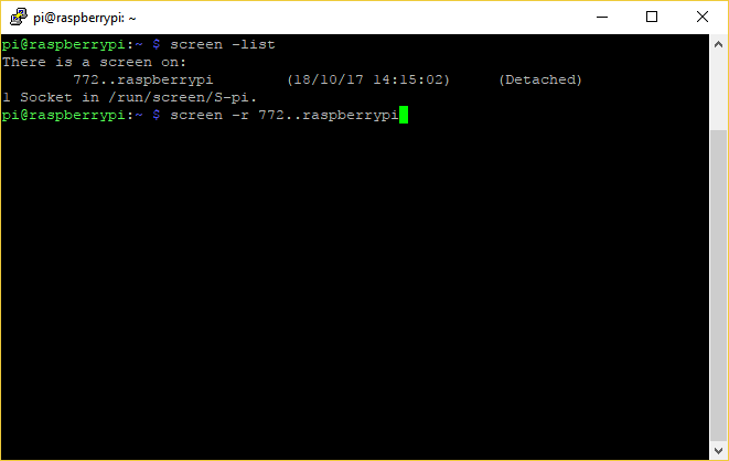 Press enter, and then see your terminal output.
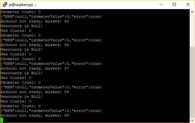 For more info on how to use screen, check out this link:
https://www.gnu.org/software/screen/manual/screen.html

For my senior thesis project at WPI, myself and two colleagues (Rachael Putnam – RBE/ME and Mead Landis – RBE/ME) designed a tree climbing robot. I was in charge of designing and implementing the electronics and controls software. I was the most intense project I have ever worked on, both in terms of difficulty and potential impact. Here is our poster for project presentation day:

Here’s a video of the prototype climbing:
We did a blog during the project, here is the best post I wrote:
The report is massive, check it out here: https://digital.wpi.edu/concern/student_works/s4655j16f?locale=en