This is a short post illustrating the process of planting the seeds.


This is a short post illustrating the process of planting the seeds.

Long time viewers will remember when this idea was conceived two Novembers ago, but essentially it’s a way to detect the relative moisture of a substance.
The principal is the same as in the above post, but this time, I made it bigger and attached it to a Raspberry Pi. The reason this is essential, is because I recently purchased a 12v DC pump capable of moving water. I will be able to sense the relative moisture in the plant, and then the plant will be able to water “itself”.
That will be done in python with the same basic technique I’ve been using all along, but in addition to gathering data about the plant every hour or so, it will be able to see if the plant needs water (by checking hopefully an array of moisture sensors) and then turning on the pump and watering it. I will also eventually integrate twitter and a webcam, but those cosmetic editions come once I know the system works.
To test it, I’ve added another set of data to the graph as seen in the last post and created a testing environment in my windowsill.
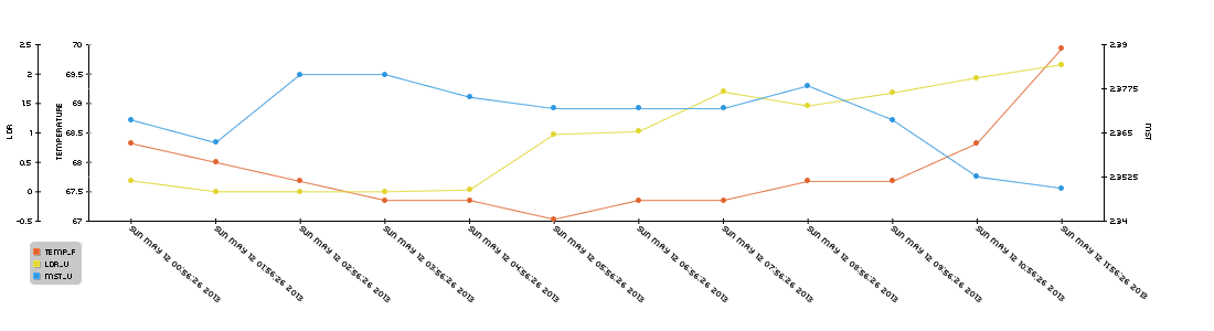
Basically I’ve put some dirt and 100mL of water into a container and inserted the sensor and am monitoring the moisture level over the next n hours, here are some pictures:





And here is a graph of some of the data:
I will make another post later today illustrating the process of plating the seeds.

Time to get this data we’re harvesting graphed. In a couple past posts, I’ve used pChart to graph random data but now since data is getting dumped into a mysql chart, it would make sense to try and graph that data.
To install pChart on my system (same installs as listed in this post) to do that do the following:
First, get the php5-gd package by running:
|
1 |
sudo apt-get install php5-gd |
Then download, rename and move the pChart files to the proper directory:
|
1 2 3 4 |
sudo mkdir /srv/www/lib/ sudo wget http://www.pchart.net/release/pChart2.1.3.tar.gz sudo tar -xzvf pChart2.1.3.tar.gz sudo mv pChart2.1.3 pChart |
Now pChart is ready to be used.
I used a lot of the info found here:
http://wiki.pchart.net/doc.mysql.integration.html
http://wiki.pchart.net/doc.doc.draw.scale.html
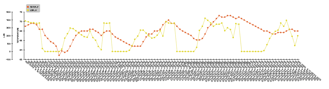
The code is pretty well commented so I’m not really going to get into describing it, but essentially, the following php will retrieve data from a mysql table (which is being populated by a python script seen in this post) and after leaving it on in my room for like 3 days, render this graph:
Here’s that php script:
|
1 2 3 4 5 6 7 8 9 10 11 12 13 14 15 16 17 18 19 20 21 22 23 24 25 26 27 28 29 30 31 32 33 34 35 36 37 38 39 40 41 42 43 44 45 46 47 48 49 50 51 52 53 54 55 56 57 58 59 60 61 62 63 |
<?php /* Include all the classes */ include("/srv/www/lib/pChart/class/pData.class.php"); include("/srv/www/lib/pChart/class/pDraw.class.php"); include("/srv/www/lib/pChart/class/pImage.class.php"); /* Create your dataset object */ $myData = new pData(); $db = mysql_connect("localhost", "piplanter_user", "piplanter_pass"); //location of server, db username, db pass mysql_select_db("piplanter", $db); $Requete = "SELECT * FROM `piplanter_table_05`"; //table name $Result = mysql_query($Requete, $db); /*This fetches the data from the mysql database, and adds it to pchart as points*/ while($row = mysql_fetch_array($Result)) { //$Sample_Number = $row["Sample_Number"]; //Not using this data //$myData->addPoints($Sample_Number,"Sample_Number"); $Time = $row["Time"]; $myData->addPoints($Time,"Time"); $Temp_F = $row["Temp_F"]; $myData->addPoints($Temp_F,"Temp_F"); $LDR_V = $row["LDR_V"]; $myData->addPoints($LDR_V,"LDR_V"); } $myData-> setSerieOnAxis("Temp_F", 0); //assigns the data to the frist axis $myData-> setAxisName(0, "Temperature"); //adds the label to the first axis $myData-> setSerieOnAxis("LDR_V", 1); $myData-> setAxisName(1, "LDR"); $myData-> setAxisPosition(1,AXIS_POSITION_LEFT); //moves the second axis to the far left $myData->setAbscissa("Time"); //sets the time data set as the x axis label $myPicture = new pImage(1100,300,$myData); /* Create a pChart object and associate your dataset */ $myPicture->setFontProperties(array("FontName"=>"/srv/www/lib/pChart/fonts/pf_arma_five.ttf","FontSize"=>6)); /* Choose a nice font */ $myPicture->setGraphArea(80,40,1000,200); /* Define the boundaries of the graph area */ $Settings = array("R"=>250, "G"=>250, "B"=>250, "Dash"=>1, "DashR"=>0, "DashG"=>0, "DashB"=>0); $myPicture->drawScale(array("LabelRotation"=>320)); /* Draw the scale, keep everything automatic */ /*The combination makes a cool looking graph*/ $myPicture->drawPlotChart(); $myPicture->drawLineChart(); $myPicture->drawLegend(90,20); //adds the legend $myPicture->autoOutput(); /* Build the PNG file and send it to the web browser */ ?> |
I’m in a hotel trying to occupy myself with something interesting so I’ve decided to work on this. I had to re-image the SD card I’ve been developing this project on, but I saved to code so there’s no problem there. Now I need to re-install all the basic packages.
First I need to get the components of a LAMP server with the following commands:
|
1 2 3 4 5 |
sudo apt-get install apache2 sudo apt-get install mysql-server sudo apt-get install php5 sudo apt-get install php5-server sudo apt-get install php5-mysql |
Once you get the mysql server setup, you’ll need to create a database and tables in mysql.
To create the database you’ll be using run the following command:
|
1 |
CREATE DATABASE piplanter; |
And then grant the proper privileges to use later with the command:
|
1 2 |
mysql> mysql> GRANT ALL PRIVILEGES ON piplanter.* TO 'user'@'localhost' IDENTIFIED BY 'pass'; FLUSH PRIVILEGES; |
Then we can enter the database and create a table:
|
1 2 |
USE piplanter; CREATE TABLE piplanter_table_01(Sample_Number INT NOT NULL AUTO_INCREMENT PRIMARY KEY, Time VARCHAR(100), Temp_F VARCHAR(100), LDR_V VARCHAR(100) ); |
Now we need to set up the specific libraries for python the first of which being spidev, the spi tool for the raspberry pi which we can grab from git using the following commands:
|
1 2 3 4 5 |
sudo apt-get install git git clone git://github.com/doceme/py-spidev cd py-spidev/ sudo apt-get install python-dev sudo python setup.py install |
You also need to (copied from http://scruss.com/blog/2013/01/19/the-quite-rubbish-clock/):
As root, edit the kernel module blacklist file:
|
1 |
sudo vi /etc/modprobe.d/raspi-blacklist.conf |
Comment out the spi-bcm2708 line so it looks like this:
|
1 |
#blacklist spi-bcm2708 |
Save the file so that the module will load on future reboots. To enable the module now, enter:
|
1 |
sudo modprobe spi-bcm2708 |
We will also need WiringPi:
|
1 2 3 |
sudo apt-get install python-imaging python-imaging-tk python-pip python-dev git sudo pip install spidev sudo pip install wiringpi |
Then you need to get APscheduler, the timing program used to execute the incremental timing with the following commands:
|
1 2 3 |
wget https://pypi.python.org/packages/source/A/APScheduler/APScheduler-2.1.0.tar.gz sudo tar -xzvf APScheduler-2.1.0.tar.gz python setup.py install |
You will need mysqldb to interface python and mysql:
|
1 |
sudo apt-get install python-mysqldb |
Once you reboot, the following program should work:
|
1 2 3 4 5 6 7 8 9 10 11 12 13 14 15 16 17 18 19 20 21 22 23 24 25 26 27 28 29 30 31 32 33 34 35 36 37 38 39 40 41 42 43 44 45 46 47 48 49 50 51 52 53 54 55 56 57 58 59 60 61 62 63 64 65 66 67 68 69 70 71 72 73 74 75 76 77 78 79 80 81 82 |
#Timing setup from datetime import datetime from apscheduler.scheduler import Scheduler import time import datetime import sys now =datetime.datetime.now() import logging #if you start getting logging errors, uncomment these two lines logging.basicConfig() #GPIO setup import RPi.GPIO as GPIO GPIO.setmode(GPIO.BOARD) GPIO.cleanup() pin = 26 #pin for the adc GPIO.setup(pin, GPIO.OUT) led1 = 11 #pin for the short indicator led GPIO.setup(led1, GPIO.OUT) led2 = 13 #pin for other long indicator led GPIO.setup(led2, GPIO.OUT) #the adc's SPI setup import spidev spi = spidev.SpiDev() spi.open(0, 0) import MySQLdb con = MySQLdb.connect('localhost','piplanter_user','piplanter_pass','piplanter'); cursor = con.cursor() #fuction that can read the adc def readadc(adcnum): # read SPI data from MCP3008 chip, 8 possible adc's (0 thru 7) if adcnum > 7 or adcnum < 0: return -1 r = spi.xfer2([1, 8 + adcnum << 4, 0]) adcout = ((r[1] & 3) << 8) + r[2] return adcout def rapidSample(): sampleTime = time.ctime() sampleTemp1 = (((readadc(0)*3.3)/1024)/(10.0/1000)) #this translates the analog voltage to temperature in def F sampleLght1 = readadc(1) samplePot1 = readadc(2) GPIO.output(led1, True) #turns the led on time.sleep(.1) #sleeps a little bit so you can see the LED on print "Job 1", sampleTime,"LDR:",sampleLght1 ,"Pot:",samplePot1,"Temp:",sampleTemp1 #prints the debug info cursor.execute("INSERT INTO piplanter_table_02(Time,Temp_F,LDR_V) VALUES(%s,'%s','%s')",(sampleTime,sampleTemp1,sampleLght1)) con.commit() #this is important for live updating time.sleep(.1) GPIO.output(led1, False) #turns the led off def slowSample(): sampleTime = time.ctime() sampleTemp1 = (((readadc(0)*3.3)/1024)/(10.0/1000)) #this translates the analog voltage to temperature in def F sampleLght1 = readadc(1) samplePot1 = readadc(2) GPIO.output(led2, True) #turns the led on time.sleep(5) print "Job 2", sampleTime,"LDR:",sampleLght1 ,"Pot:",samplePot1,"Temp:",sampleTemp1 #prints the debug info cursor.execute("INSERT INTO piplanter_table_03(Time,Temp_F,LDR_V) VALUES(%s,'%s','%s')",(sampleTime,sampleTemp1,sampleLght1)) con.commit() #this is important for live updating time.sleep(5) GPIO.output(led2, False) #turns the led on if __name__ == '__main__': #the following 3 lines start up the interval job and keep it going scheduler = Scheduler(standalone=True) scheduler.add_interval_job(rapidSample, minutes=1) scheduler.add_interval_job(slowSample, hours=1) scheduler.start() |
And there you go! The program should log data every minute and then every hour to two different tables. To view those data sets as php tables you can use this php script:
|
1 2 3 4 5 6 7 8 9 10 11 12 13 14 15 16 17 18 19 20 21 22 23 24 25 26 |
<?php mysql_connect("localhost", "piplanter_user","piplanter_pass") or die ("Could not connect: " . mysql_error()); mysql_select_db("piplanter"); $result = mysql_query("SELECT * FROM piplanter_table_02"); echo "<table border='1'> <tr> <th>Sample_Number</th> <th>Time</th> <th>Temp F</th> <th>LDR Value V</th> </tr>"; while($row = mysql_fetch_array($result)){ echo"<tr>"; echo"<td>" . $row['Sample_Number'] . "</td>"; echo"<td>" . $row['Time'] . "</td>"; echo"<td>" . $row['Temp_F'] . "</td>"; echo"<td>" . $row['LDR_V'] . "</td>"; echo"</tr>"; } echo "</table>"; mysql_close($con); ?> |
Sometime later I’ll get to graphing the data.
I’m taking a “break” from my drone while I save some money to buy more tricopter parts, and since the weather’s getting nicer and nicer I’ve decided to start working on my PiPlanter again.
As a refresher, the PiPlanter is a Raspberry Pi powered garden. The goal is for it to just be able to be plugged in and add water to a water source and have the Pi monitor temp and moisture levels to be able to add more water as needed.
I’ve shown that is relatively easy to go from analog sensors to good looking tables and graphs using the raspberry pi, the problem that I ran into however was timing.
It became harder and harder to use the time.sleep function in python to handle long periods of time. When you are dealing with things like plants, you don’t need to water it very often, but for data’s sake, you should be polling the sensors a lot.
I’ve landed on the use of APScheduler in python, and here’s my source code:
[py]
#Timing setup
from datetime import datetime
from apscheduler.scheduler import Scheduler
import time
import logging #if you start getting logging errors, uncomment these two lines
logging.basicConfig()
#GPIO setup
import RPi.GPIO as GPIO
GPIO.setmode(GPIO.BOARD)
GPIO.cleanup()
pin = 26 #pin for the adc
GPIO.setup(pin, GPIO.OUT)
led1 = 11 #pin for the short indicator led
GPIO.setup(led1, GPIO.OUT)
led2 = 13 #pin for other long indicator led
GPIO.setup(led2, GPIO.OUT)
#the adc’s SPI setup
import spidev
spi = spidev.SpiDev()
spi.open(0, 0)
going = True
#fuction that can read the adc
def readadc(adcnum):
# read SPI data from MCP3008 chip, 8 possible adc’s (0 thru 7)
if adcnum > 7 or adcnum < 0:
return -1
r = spi.xfer2([1, 8 + adcnum << 4, 0])
adcout = ((r[1] & 3) << 8) + r[2]
return adcout
def rapidSample():
sampleTemp1 = (((readadc(0)*3.3)/1024)/(10.0/1000)) #this translates the analog voltage to temperature in def F
sampleLght1 = readadc(1)
samplePot1 = readadc(2)
GPIO.output(led1, True) #turns the led on
time.sleep(.1) #sleeps a little bit so you can see the LED on
print “Job 1″, datetime.now(),”LDR:”,sampleLght1 ,”Pot:”,samplePot1,”Temp:”,sampleTemp1 #prints the debug info
time.sleep(.1)
GPIO.output(led1, False) #turns the led off
def slowSample():
print “Job 2” , datetime.now()
GPIO.output(led2, True) #turns the led on
time.sleep(5)
GPIO.output(led2, False) #turns the led on
if __name__ == ‘__main__’:
#the following 3 lines start up the interval job and keep it going
scheduler = Scheduler(standalone=True)
scheduler.add_interval_job(rapidSample, seconds=1)
scheduler.add_interval_job(slowSample, minutes=1)
scheduler.start()
[/py]
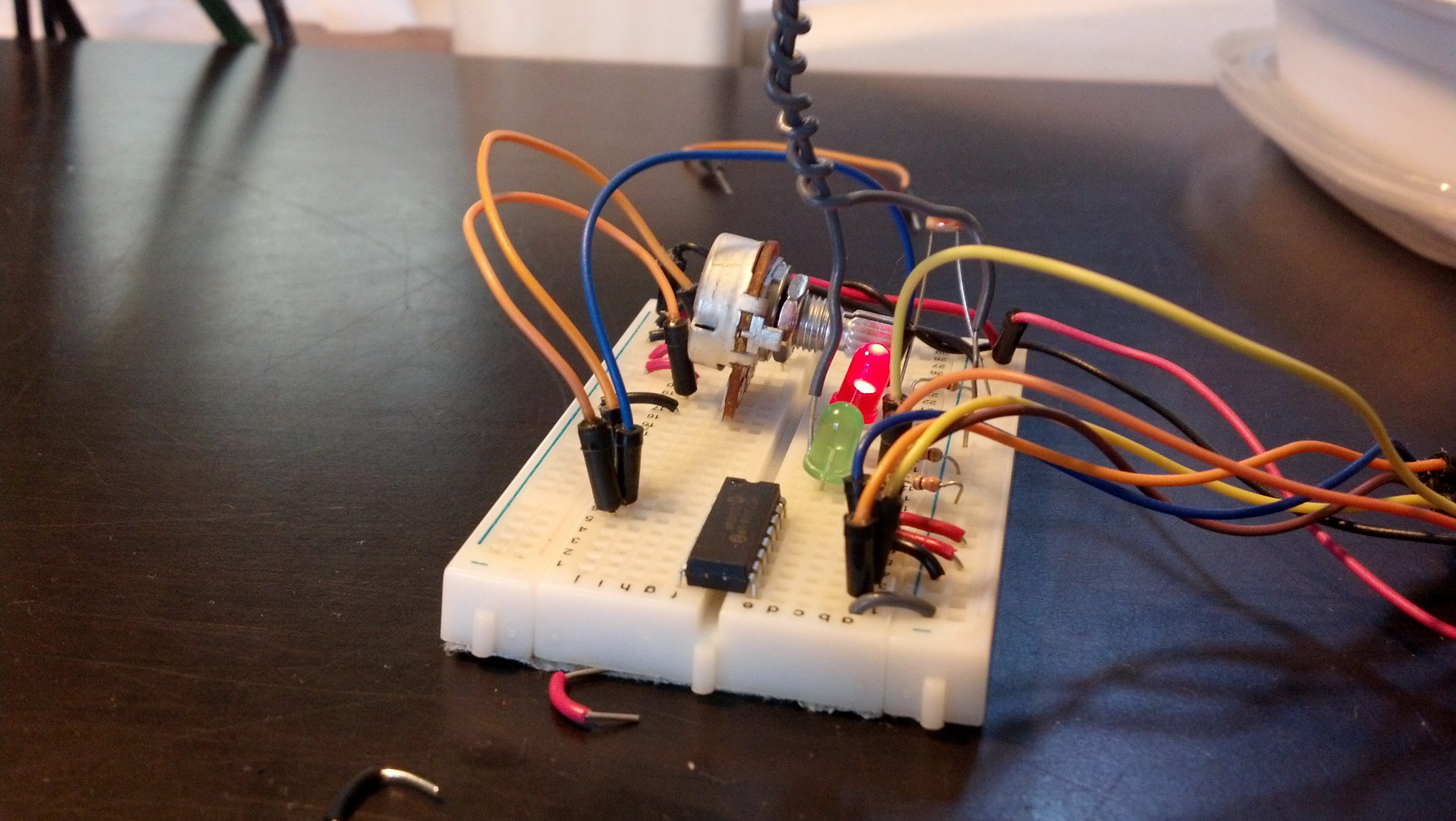
This produces a loop that flashed a green led on and of for .1 seconds at a time per second, and then every minute, turns on a speaker and a red led for 5 seconds then turns it off. There are some images of what goes on below.
Here is a picture of the the print dialog in python:
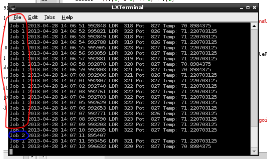
You can see that the first job (green led) posts the values from the analog sensors every second
The second job (red led) just posts the time. But the function is expandable to do anything at any time.
Here are pictures of the board and the circuit in action:
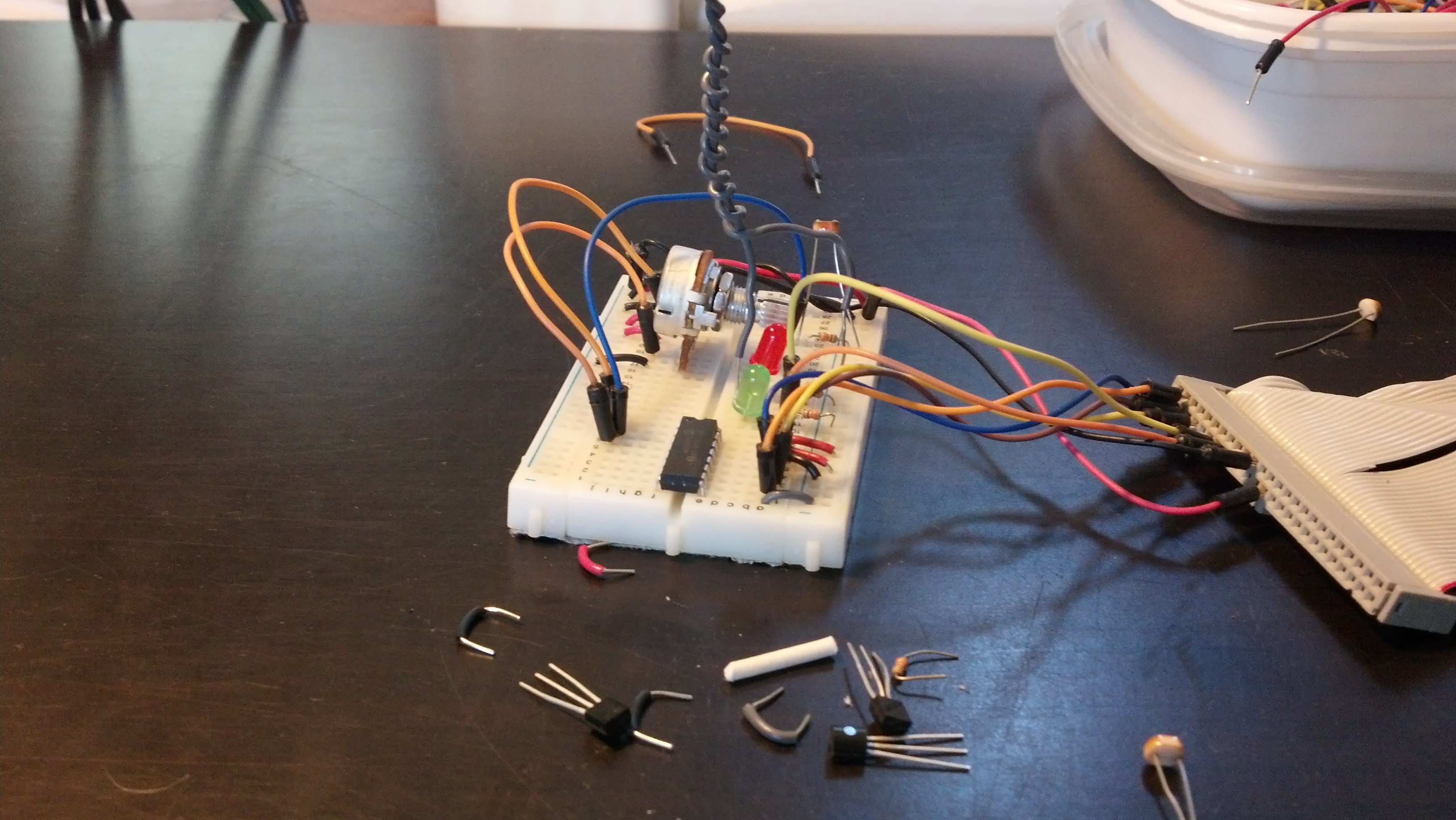
Both LED’s off
The Green LED on, the red circled process in the printout
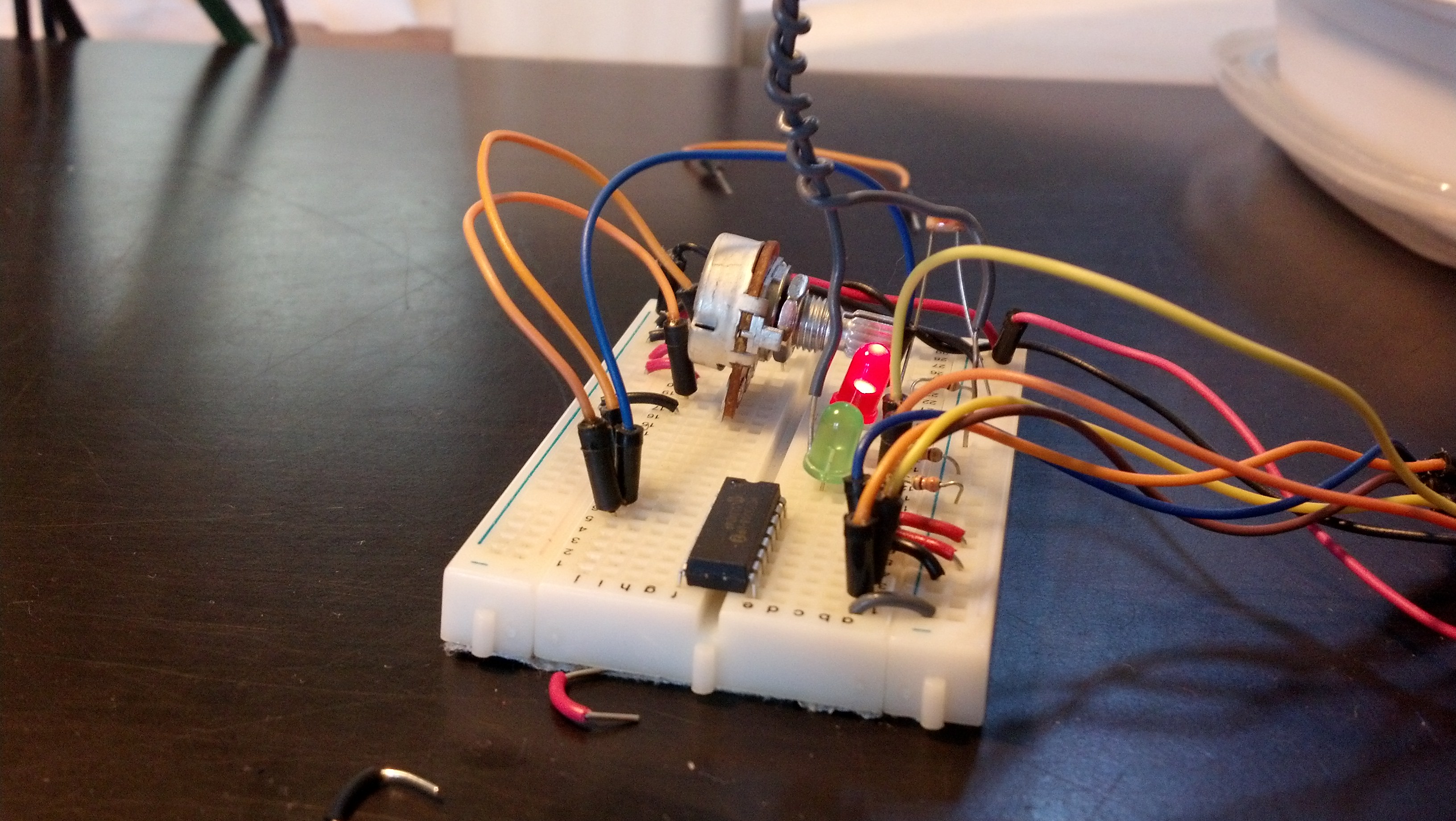
Here are both on
The next step is adding the mySQL in as seen in some other posts.

So here’s a video:
So pretty easy but important step here. For a while I’ve known that I need to have some more feedback from the robot that just LED brightness levels on the controller. This VB program allows me to get analog values from the vehicle and interpret them in any number of ways. You can download and run that program HERE, and like I said in the video I’ve refrained from going open source with my VB programs in the past because they’ve never really had any polish to them. But now I think it will be good to keep this all open.
I also added a 16 * 2 character LCD to my controller. I’ve sacrificed the 6 pins because hopefully in the long run it will be a better experience for the user. I may go back, but for now I’d rather build around something that’s a little more constraining as it will force me to innovate a little bit more. Here’s a picture of the new controller:
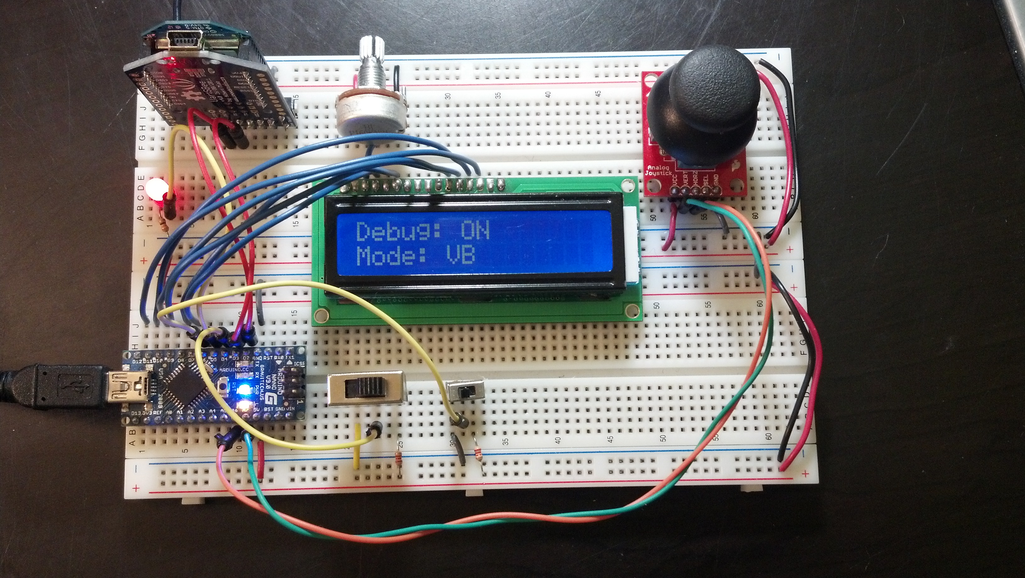
Here’s the program:
|
1 2 3 4 5 6 7 8 9 10 11 12 13 14 15 16 17 18 19 20 21 22 23 24 25 26 27 28 29 30 31 32 33 34 35 36 37 38 39 40 41 42 43 44 45 46 47 48 49 50 51 52 53 54 55 56 57 58 59 60 61 62 63 64 65 66 67 68 69 70 71 72 73 74 75 76 77 78 79 80 81 82 83 84 85 86 87 88 89 90 91 92 93 94 95 96 97 98 99 100 101 102 103 104 105 106 107 108 109 110 111 112 113 114 115 116 117 118 119 120 121 122 123 124 125 126 127 128 129 130 131 132 133 134 135 136 137 138 139 140 141 142 143 144 145 146 147 148 149 150 151 152 153 154 155 156 157 158 159 160 161 162 163 164 165 166 167 168 169 170 171 172 173 174 175 176 177 178 179 180 181 182 183 184 185 186 187 188 189 190 191 192 193 194 195 196 197 198 199 200 201 202 203 204 205 206 207 208 209 210 211 212 213 214 215 216 217 218 219 220 221 222 223 224 225 226 227 228 229 230 231 232 233 234 235 236 237 238 239 240 241 242 243 244 245 246 247 248 249 250 251 252 253 254 255 256 257 258 259 260 261 262 263 264 265 266 267 268 269 270 271 272 273 274 275 276 277 278 279 280 |
//Serial Handshake declaration #include <string.h> // we'll need this for subString #define MAX_STRING_LEN 100 // like 3 lines above, change as needed. const char EOPmarker = '.'; //This is the end of packet marker char serialbuf[100]; //This gives the incoming serial some room. Change it if you want a longer incoming. //SoftwareSerial declaration #include <SoftwareSerial.h> SoftwareSerial xbee_serial(2, 3); //Shift Register Pins declaration int SER_Pin = 5; //pin 14 on the 75HC595 int RCLK_Pin = 6; //pin 12 on the 75HC595 int SRCLK_Pin = 7; //pin 11 on the 75HC595 #define number_of_74hc595s 1 //How many of the shift registers - change this #define numOfRegisterPins number_of_74hc595s * 8 //do not touch boolean registers[numOfRegisterPins]; //Servo declarations int left_servo_val; int rght_servo_val; //lcd declaration #include <LiquidCrystal.h> LiquidCrystal lcd(7, 8, 9, 10, 11, 12); //Misc Pin declaration //inputs int debug_switch1 = 4; int debug_switch2 = 6; //these values are for communication, not hardware inputs int in_ref; int in_brightness; int in_pot1; int in_pot2; int in_accelerometer_x; int in_accelerometer_y; int in_accelerometer_z; int in_temp1; //outputs //int pot_LED = 6; int fade_LED = 5; int debug_switch1_LED = 13; //these values are for communication, not hardware outputs int out_joystick_x; int out_joystick_y; //Misc Integer Declarations int brightness = 0; // how bright the LED is int fadeAmount = 51; // how many points to fade the LED by int accel_x_min = 293; int accel_x_max = 440; int accel_y_min = 290; int accel_y_max = 434; void setup(){ Serial.begin(9600); xbee_serial.begin(9600); //shift register setup pinMode(SER_Pin, OUTPUT); pinMode(RCLK_Pin, OUTPUT); pinMode(SRCLK_Pin, OUTPUT); pinMode(0, INPUT); clearRegisters(); writeRegisters(); //Misc Pin Declarations pinMode(debug_switch1, INPUT); pinMode(debug_switch2, INPUT); //pinMode(pot_LED, OUTPUT); pinMode(fade_LED, OUTPUT); //lcd declaration lcd.begin(16, 2); xbee_serial.print("0,0,0."); // this is very important as it starts of the loop because it makes "xbee_serial.avalible() > 0. } void loop(){ if (xbee_serial.available() > 0) { static int bufpos = 0; char inchar = xbee_serial.read(); if (inchar != EOPmarker) { serialbuf[bufpos] = inchar; bufpos++; } else { serialbuf[bufpos] = 0; //restart the buff bufpos = 0; //restart the position of the buff if (digitalRead(debug_switch1) == LOW){ digitalWrite(debug_switch1_LED, LOW); //LED in board indicates debug status handshake(); lcd.setCursor(0, 0); lcd.print("Debug: OFF"); lcd.setCursor(0, 1); lcd.print(" "); digitalWrite(debug_switch1_LED, LOW); } if (digitalRead(debug_switch1) == HIGH){ handshake(); //no matter what, the handshake happens normally lcd.setCursor(0, 0); lcd.print("Debug: ON "); debug_handshake(); //the debug to console only slows the process downm no interference with data digitalWrite(debug_switch1_LED, HIGH); } } } } void handshake(){ //inputs, recived from vehicle in_ref = atoi(subStr(serialbuf, "," , 1)); in_brightness = atoi(subStr(serialbuf, "," , 2)); in_pot1 = (map(atoi(subStr(serialbuf, "," , 3)),0,1023,0,255)); in_pot2 = atoi(subStr(serialbuf, "," , 4)); in_accelerometer_x = atoi(subStr(serialbuf, "," , 5)); in_accelerometer_y = atoi(subStr(serialbuf, "," , 6)); in_accelerometer_z = atoi(subStr(serialbuf, "," , 7)); in_temp1 = atoi(subStr(serialbuf, "," , 8)); analogWrite(fade_LED, in_brightness); //analogWrite(pot_LED, in_pot1); //outputs, sent to vehicle brightness = brightness + fadeAmount; // reverse the direction of the fading at the ends of the fade: if (brightness == 0 || brightness == 255) { fadeAmount = -fadeAmount ; } out_joystick_x = analogRead(7); //remap for coherency purposes out_joystick_y = analogRead(6); xbee_serial.print(brightness); xbee_serial.print(","); xbee_serial.print(out_joystick_x); xbee_serial.print(","); xbee_serial.print(out_joystick_y); xbee_serial.print("."); //EOP marker delay(10); } void debug_handshake() { //there are two debug modes if (digitalRead(debug_switch2) == HIGH){ lcd.setCursor(0, 1); lcd.print("Mode: 1 Line"); debug_handshake_fncy(); //this is good for looking at one line at a time (via the port monitor) } if (digitalRead(debug_switch2) == LOW){ debug_handshake_smpl(); //this is great for data interpretation (via VB) lcd.setCursor(0, 1); lcd.print("Mode: VB "); } } void debug_handshake_fncy(){ Serial.print("INPUTS {"); Serial.print("refvolt: "); Serial.print(in_ref); Serial.print(","); Serial.print(" fade: "); Serial.print(brightness); Serial.print(","); Serial.print(" LED1: "); Serial.print(in_pot1); Serial.print(","); Serial.print(" pot2: "); Serial.print(in_pot2); Serial.print(","); Serial.print(" accel_x: "); Serial.print(in_accelerometer_x); Serial.print(","); Serial.print(" accel_y: "); Serial.print(in_accelerometer_y); Serial.print(","); Serial.print(" accel_z: "); Serial.print(in_accelerometer_z); Serial.print(","); Serial.print(" temp1: "); Serial.print(in_temp1); Serial.print("}"); Serial.print(" | "); Serial.print("OUTPUTS {"); Serial.print("joystick_x: "); Serial.print(out_joystick_x); Serial.print(","); Serial.print(" joystick_y: "); Serial.print(out_joystick_y); Serial.print("}"); Serial.println(""); } void debug_handshake_smpl(){ //just inputs seperated by commas then a | then outputs seperated by commas Serial.print(in_ref); Serial.print(","); Serial.print(brightness); Serial.print(","); Serial.print(in_pot1); Serial.print(","); Serial.print(in_pot2); Serial.print(","); Serial.print(in_accelerometer_x); Serial.print(","); Serial.print(in_accelerometer_y); Serial.print(","); Serial.print(in_accelerometer_z); Serial.print(","); Serial.print(in_temp1); Serial.print(","); Serial.print("|"); Serial.print(out_joystick_x); Serial.print(","); Serial.print(out_joystick_y); Serial.println(""); } char* subStr (char* input_string, char *separator, int segment_number) { //for substring char *act, *sub, *ptr; static char copy[MAX_STRING_LEN]; int i; strcpy(copy, input_string); for (i = 1, act = copy; i <= segment_number; i++, act = NULL) { sub = strtok_r(act, separator, &ptr); if (sub == NULL) break; } return sub; } void clearRegisters(){ //for shift registers for(int i = numOfRegisterPins - 1; i >= 0; i--){ registers[i] = LOW; } } void writeRegisters(){ //for shift registers digitalWrite(RCLK_Pin, LOW); for(int i = numOfRegisterPins - 1; i >= 0; i--){ digitalWrite(SRCLK_Pin, LOW); int val = registers[i]; digitalWrite(SER_Pin, val); digitalWrite(SRCLK_Pin, HIGH); } digitalWrite(RCLK_Pin, HIGH); } //set an individual pin HIGH or LOW void setRegisterPin(int index, int value){ registers[index] = value; } |
I didn’t mention in in the video, but I moved the mux from the controller, to the vehicle. It allows me to have 22 analog inputs, and the reason I took so long to finally add it was primarily laziness on my part. Aside from the the code is still very similar but close followers will notice that I cleaned up the way the program receives and sends code. It is much much more organized, and much more expandable. Here’s the “new” controller:

Here’s the new program:
|
1 2 3 4 5 6 7 8 9 10 11 12 13 14 15 16 17 18 19 20 21 22 23 24 25 26 27 28 29 30 31 32 33 34 35 36 37 38 39 40 41 42 43 44 45 46 47 48 49 50 51 52 53 54 55 56 57 58 59 60 61 62 63 64 65 66 67 68 69 70 71 72 73 74 75 76 77 78 79 80 81 82 83 84 85 86 87 88 89 90 91 92 93 94 95 96 97 98 99 100 101 102 103 104 105 106 107 108 109 110 111 112 113 114 115 116 117 118 119 120 121 122 123 124 125 126 127 128 129 130 131 132 133 134 135 136 137 138 139 140 141 142 143 144 145 146 147 148 149 150 151 152 153 154 155 156 157 158 159 160 161 162 163 164 165 166 167 168 169 170 171 172 173 174 175 176 177 178 179 180 181 182 183 184 185 186 187 188 189 190 191 192 193 194 195 196 197 198 199 200 201 202 203 204 205 206 207 208 209 210 211 212 213 214 215 216 217 218 219 220 221 222 223 224 225 226 227 228 229 230 231 232 233 234 235 236 237 238 239 240 241 242 243 244 245 246 247 248 249 250 251 252 253 254 255 256 257 258 259 260 261 262 263 264 265 266 267 268 269 270 271 272 273 274 275 276 |
//Serial Handshake declaration #include <string.h> // we'll need this for subString #define MAX_STRING_LEN 100 // like 3 lines above, change as needed. const char EOPmarker = '.'; //This is the end of packet marker char serialbuf[100]; //This gives the incoming serial some room. Change it if you want a longer incoming. //SoftwareSerial declaration #include <SoftwareSerial.h> SoftwareSerial xbee_serial(8, 9); //Mux control pins declarations int s0 = 2; int s1 = 3; int s2 = 4; int s3 = 7; int SIG_pin = 0; //Shift Register Pins declaration int SER_Pin = 10; //pin 14 on the 75HC595 int RCLK_Pin = 11; //pin 12 on the 75HC595 int SRCLK_Pin = 12; //pin 11 on the 75HC595 #define number_of_74hc595s 1 //How many of the shift registers - change this #define numOfRegisterPins number_of_74hc595s * 8 //do not touch boolean registers[numOfRegisterPins]; //Servo declarations #include <Servo.h> Servo left_servo; Servo rght_servo; //Misc Pin declaration //inputs int debug_switch1 = 4; //outputs //these values are for communication, not hardware outputs int out_ref; int out_pot1; int out_pot2; int out_accelerometer_x; int out_accelerometer_y; int out_accelerometer_z; int out_temp1; int fade_LED = 13; int x_LED = 5; int y_LED = 6; //int debug_switch1_LED = 12; //Misc Integer declarations int in_brightness; int in_joystick_x; int in_joystick_y; int brightness = 0; // how bright the LED is int fadeAmount = 51; // how many points to fade the LED by int x_upperTrigger = 600; int x_lowerTrigger = 450; int y_upperTrigger = 600; int y_lowerTrigger = 400; void setup(){ Serial.begin(9600); xbee_serial.begin(9600); //mux setup pinMode(s0, OUTPUT); pinMode(s1, OUTPUT); pinMode(s2, OUTPUT); pinMode(s3, OUTPUT); digitalWrite(s0, LOW); digitalWrite(s1, LOW); digitalWrite(s2, LOW); digitalWrite(s3, LOW); //shift register setup pinMode(SER_Pin, OUTPUT); pinMode(RCLK_Pin, OUTPUT); pinMode(SRCLK_Pin, OUTPUT); clearRegisters(); writeRegisters(); //misc pin declarations pinMode(x_LED, OUTPUT); pinMode(y_LED, OUTPUT); pinMode(fade_LED, OUTPUT); xbee_serial.print("0,0,0."); // this is very important as it starts of the loop because it makes "xbee_serial.avalible() > 0. } void loop(){ if (xbee_serial.available() > 0) { static int bufpos = 0; char inchar = xbee_serial.read(); if (inchar != EOPmarker) { serialbuf[bufpos] = inchar; bufpos++; } else { serialbuf[bufpos] = 0; //restart the buff bufpos = 0; //restart the position of the buff handshake(); setRegisterPin(1, HIGH); writeRegisters(); } } } void handshake(){ //inputs in_brightness = atoi(subStr(serialbuf, "," , 1)); in_joystick_x = atoi(subStr(serialbuf, "," , 2)); in_joystick_y = atoi(subStr(serialbuf, "," , 3)); analogWrite(fade_LED,in_brightness); if (in_joystick_x > x_upperTrigger){ //the below boolean blocks set pins high or low setRegisterPin(4,HIGH); setRegisterPin(5,LOW); analogWrite(x_LED, map(in_joystick_x,x_upperTrigger,1023,0,255)); writeRegisters(); } if (in_joystick_x < x_lowerTrigger){ setRegisterPin(4,LOW); setRegisterPin(5,HIGH); analogWrite(x_LED, map(in_joystick_x,x_upperTrigger,0,0,255)); writeRegisters(); } if (in_joystick_x > x_lowerTrigger && in_joystick_x < x_upperTrigger){ setRegisterPin(4,LOW); setRegisterPin(5,LOW); analogWrite(x_LED,0); writeRegisters(); } // x above y below if (in_joystick_y > y_upperTrigger){ setRegisterPin(2,HIGH); setRegisterPin(3,LOW); analogWrite(y_LED, map(in_joystick_y,y_upperTrigger,1023,0,255)); writeRegisters(); } if (in_joystick_y < y_lowerTrigger){ setRegisterPin(2,LOW); setRegisterPin(3,HIGH); analogWrite(y_LED, map(in_joystick_y,y_upperTrigger,0,0,255)); writeRegisters(); } if (in_joystick_y > y_lowerTrigger && in_joystick_y < y_upperTrigger){ setRegisterPin(2,LOW); setRegisterPin(3,LOW); analogWrite(y_LED,0); writeRegisters(); } //outputs brightness = brightness + fadeAmount; // reverse the direction of the fading at the ends of the fade: if (brightness == 0 || brightness == 255) { fadeAmount = -fadeAmount ; } out_ref = readMux(15); out_pot1 = readMux(0); out_pot2 = readMux(1); out_accelerometer_x = readMux(2); out_accelerometer_y = readMux(3); out_accelerometer_z = readMux(4); out_temp1 = readMux(5); xbee_serial.print(out_ref); xbee_serial.print(","); xbee_serial.print(brightness); xbee_serial.print(","); xbee_serial.print(out_pot1); xbee_serial.print(","); xbee_serial.print(out_pot2); xbee_serial.print(","); xbee_serial.print(out_accelerometer_x); xbee_serial.print(","); xbee_serial.print(out_accelerometer_y); xbee_serial.print(","); xbee_serial.print(out_accelerometer_z); xbee_serial.print(","); xbee_serial.print(out_temp1); xbee_serial.print("."); //EOP marker delay(10); } // for substring char* subStr (char* input_string, char *separator, int segment_number) { char *act, *sub, *ptr; static char copy[MAX_STRING_LEN]; int i; strcpy(copy, input_string); for (i = 1, act = copy; i <= segment_number; i++, act = NULL) { sub = strtok_r(act, separator, &ptr); if (sub == NULL) break; } return sub; } // for mux int readMux(int channel){ int controlPin[] = {s0, s1, s2, s3}; int muxChannel[16][4]={ {0,0,0,0}, //channel 0 {1,0,0,0}, //channel 1 {0,1,0,0}, //channel 2 {1,1,0,0}, //channel 3 {0,0,1,0}, //channel 4 {1,0,1,0}, //channel 5 {0,1,1,0}, //channel 6 {1,1,1,0}, //channel 7 {0,0,0,1}, //channel 8 {1,0,0,1}, //channel 9 {0,1,0,1}, //channel 10 {1,1,0,1}, //channel 11 {0,0,1,1}, //channel 12 {1,0,1,1}, //channel 13 {0,1,1,1}, //channel 14 {1,1,1,1} //channel 15 }; //loop through the 4 sig for(int i = 0; i < 4; i ++){ digitalWrite(controlPin[i], muxChannel[channel][i]); } //read the value at the SIG pin int val = analogRead(SIG_pin); //return the value return val; } // for shift registers void clearRegisters(){ for(int i = numOfRegisterPins - 1; i >= 0; i--){ registers[i] = LOW; } } // for shift registers void writeRegisters(){ digitalWrite(RCLK_Pin, LOW); for(int i = numOfRegisterPins - 1; i >= 0; i--){ digitalWrite(SRCLK_Pin, LOW); int val = registers[i]; digitalWrite(SER_Pin, val); digitalWrite(SRCLK_Pin, HIGH); } digitalWrite(RCLK_Pin, HIGH); } //set an individual pin HIGH or LOW void setRegisterPin(int index, int value){ registers[index] = value; } |
Like I promised in the video, here are a few more properly focused pictures:
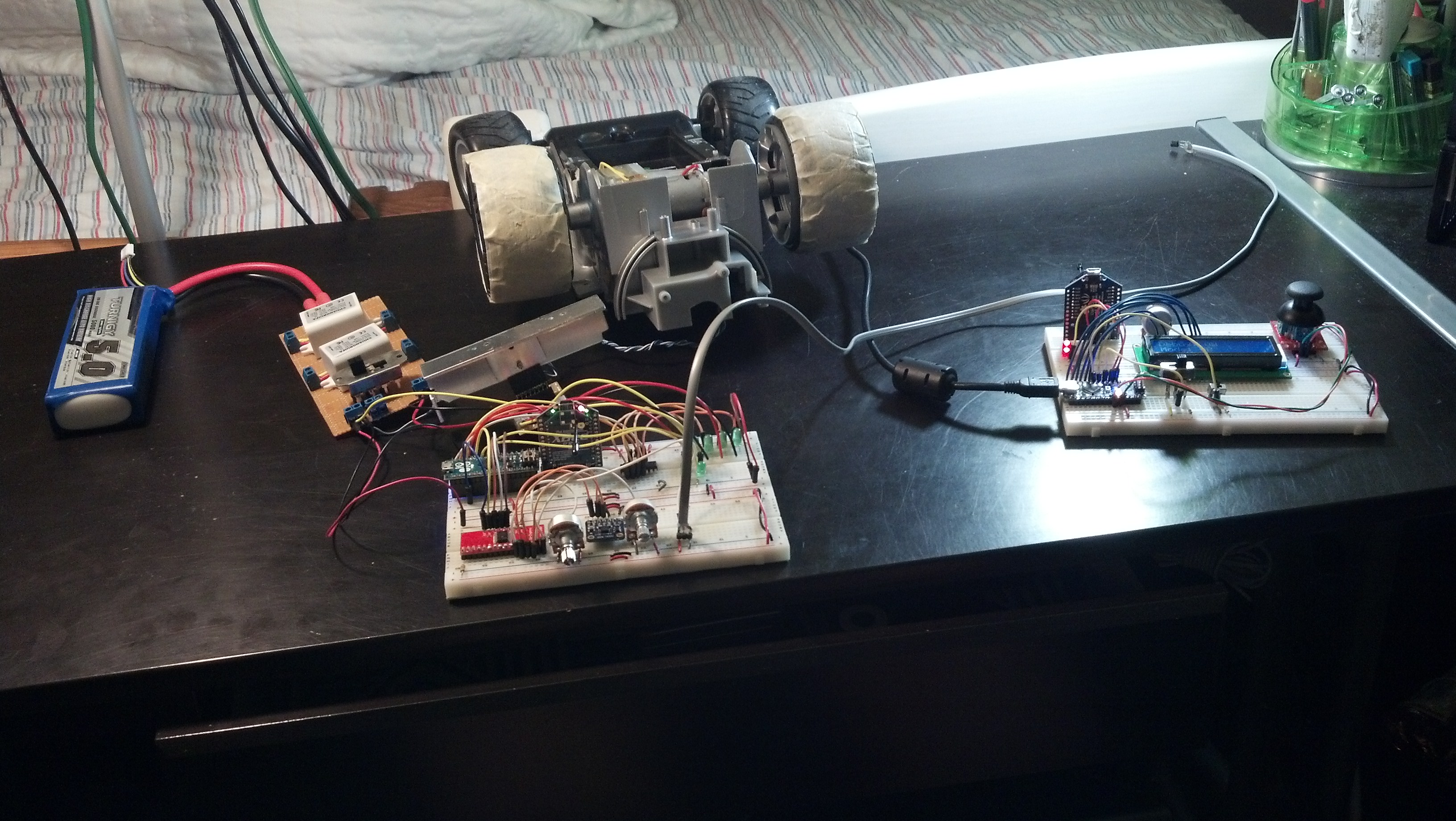
So as school and sports start to ramp up, it’s going to get harder and harder to make time for this project as I want to complete it by the first week of summer.
I made some huge progress today, but it’s really still a baby step, the proof of concept using a brushless motor was reassuring that this will be expandable into something that is powered by brushless motors (some kind of tricopter) but there’s still quite a lot to get done.
First things first, I’d like to get started on re-tooling “Vehicle_Companion” to fit the needs of this new communication protocol I’ve established. Before it acted as an intermediate between the Arduinos, and now it shouldn’t have any effect on that at all, and should only supply visual feedback from the controller.
Reason being is that I need to get more feedback from the drone than led brightness levels. Plus I’m getting a little tired of C, it’ll be good to get back into VB for a while.
I also need to come up with a way to power the controller. Plain and simple it doesn’t make sense that it’s still tied to a computer.
After that I need to start locking down the vehicle’s PCB. I don’t need to do this to the controller as it’s BOUND to go through countless revisions as the vehicle does. Since the RC car is going to be able to be operated basically with just the joystick, It wouldn’t make sense to over complicate things. Here’s a preview of what it may look like.
After that it’s time to make some decisions on what the final form of this thing is going to be, I go back and forth because of a few reasons but for now I that some sort of multirotor is going to be the best.

Pretty big day for me today. Here’s a video:
I’m pretty proud of this one, the only problem of this is that the l298N get’s too hot, you can see in the pictures that I’ve installed a makeshift heatsink but it still get’s really hot:
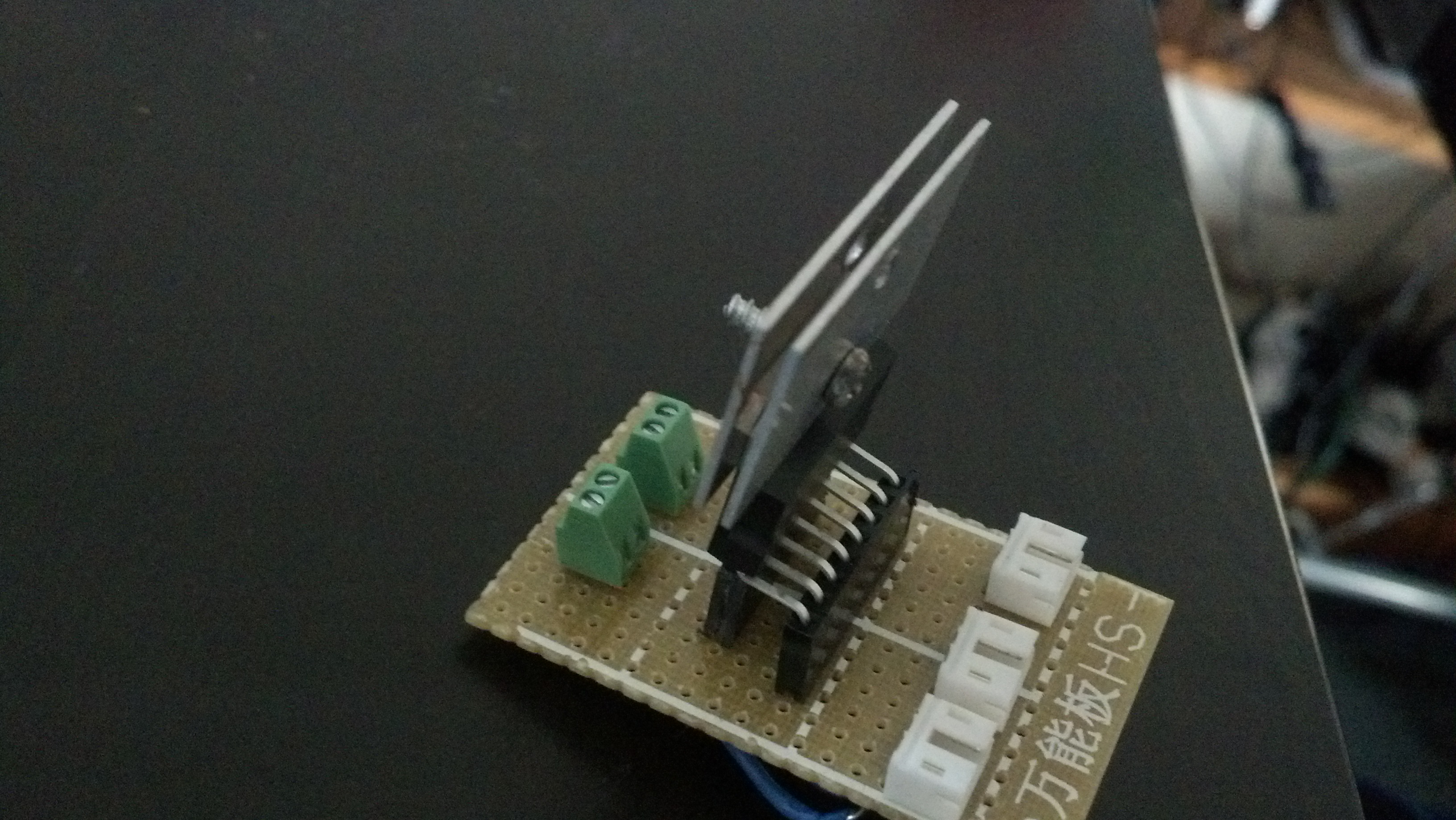
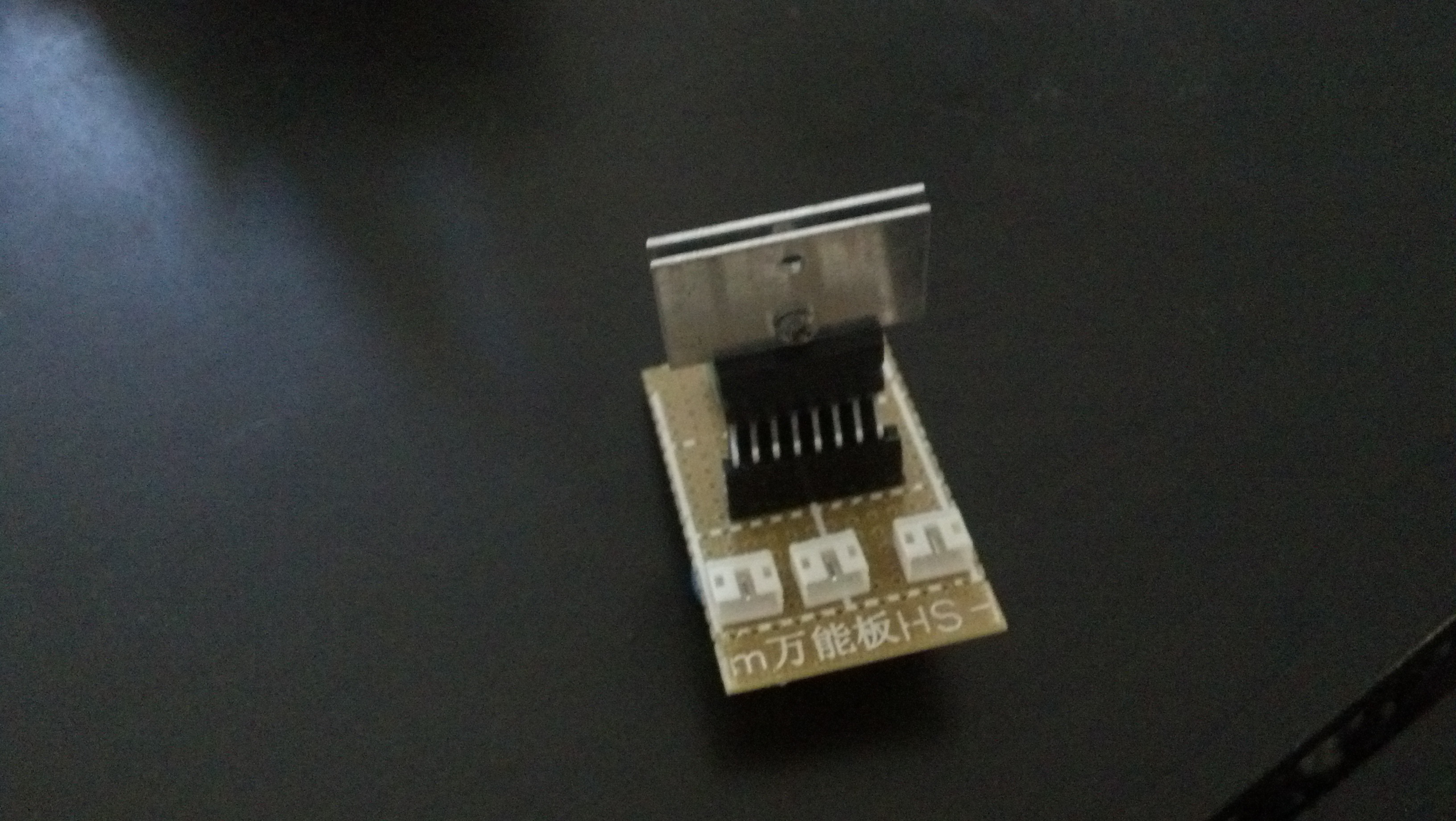
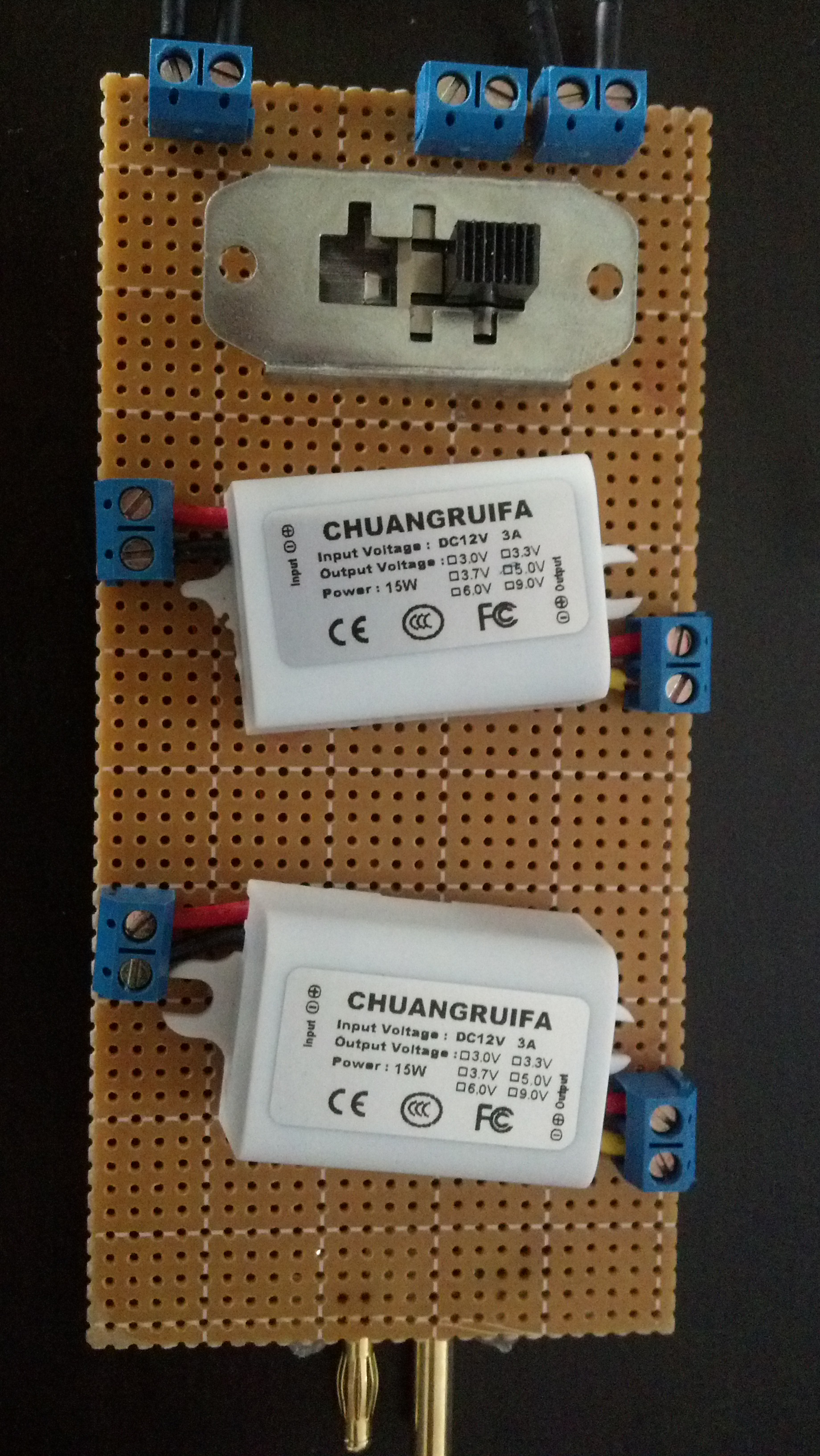
I also installed the 5v@3a regulator I mentioned in the last post, here are some pictures:
Here’s the vehicle code:
|
1 2 3 4 5 6 7 8 9 10 11 12 13 14 15 16 17 18 19 20 21 22 23 24 25 26 27 28 29 30 31 32 33 34 35 36 37 38 39 40 41 42 43 44 45 46 47 48 49 50 51 52 53 54 55 56 57 58 59 60 61 62 63 64 65 66 67 68 69 70 71 72 73 74 75 76 77 78 79 80 81 82 83 84 85 86 87 88 89 90 91 92 93 94 95 96 97 98 99 100 101 102 103 104 105 106 107 108 109 110 111 112 113 114 115 116 117 118 119 120 121 122 123 124 125 126 127 128 129 130 131 132 133 134 135 136 137 138 139 140 141 142 143 144 145 146 147 148 149 150 151 152 153 154 155 156 157 158 159 160 161 162 163 164 165 166 167 168 169 170 171 172 173 174 175 176 177 178 179 180 181 182 183 184 185 186 187 188 189 190 191 192 193 194 195 196 197 198 199 200 201 202 203 204 205 206 |
//Serial Handshake declaration #include // we'll need this for subString #define MAX_STRING_LEN 20 // like 3 lines above, change as needed. const char EOPmarker = '.'; //This is the end of packet marker char serialbuf[32]; //This gives the incoming serial some room. Change it if you want a longer incoming. //SoftwareSerial declaration #include SoftwareSerial xbee_serial(8, 9); //Shift Register Pins declaration int SER_Pin = 10; //pin 14 on the 75HC595 int RCLK_Pin = 11; //pin 12 on the 75HC595 int SRCLK_Pin = 12; //pin 11 on the 75HC595 #define number_of_74hc595s 1 //How many of the shift registers - change this #define numOfRegisterPins number_of_74hc595s * 8 //do not touch boolean registers[numOfRegisterPins]; //Servo declarations #include Servo left_servo; Servo rght_servo; //Misc Pin declaration //inputs int pot = 1; int debug_switch1 = 4; //outputs int fade_LED = 13; int x_LED = 5; int y_LED = 6; //int debug_switch1_LED = 12; //Misc Integer declarations int brightness = 0; // how bright the LED is int fadeAmount = 20; // how many points to fade the LED by int x_upperTrigger = 600; int x_lowerTrigger = 400; int y_upperTrigger = 600; int y_lowerTrigger = 400; void setup(){ Serial.begin(9600); xbee_serial.begin(9600); pinMode(SER_Pin, OUTPUT); pinMode(RCLK_Pin, OUTPUT); pinMode(SRCLK_Pin, OUTPUT); pinMode(0, INPUT); clearRegisters(); writeRegisters(); pinMode(pot, INPUT); pinMode(debug_switch1, INPUT); pinMode(x_LED, OUTPUT); pinMode(y_LED, OUTPUT); pinMode(fade_LED, OUTPUT); xbee_serial.print("0,0,0."); // this is very important as it starts of the loop because it makes "xbee_serial.avalible() > 0. } void loop(){ if (xbee_serial.available() > 0) { static int bufpos = 0; char inchar = xbee_serial.read(); if (inchar != EOPmarker) { serialbuf[bufpos] = inchar; bufpos++; } else { serialbuf[bufpos] = 0; //restart the buff bufpos = 0; //restart the position of the buff handshake(); debug_handshake(); setRegisterPin(1, HIGH); writeRegisters(); } } } void handshake(){ //input, recived from controller // led1val,ledval2,fade_LEDvalue. //analogWrite(x_LED, map(atoi(subStr(serialbuf, "," , 1)),0,1023,0,255)); //analogWrite(y_LED, map(atoi(subStr(serialbuf, "," , 2)),0,1023,0,255)); analogWrite(fade_LED, atoi(subStr(serialbuf, "," , 3))); brightness = brightness + fadeAmount; // reverse the direction of the fading at the ends of the fade: if (brightness == 0 || brightness == 255) { fadeAmount = -fadeAmount ; } if (atoi(subStr(serialbuf, "," , 1)) > x_upperTrigger ){ analogWrite(x_LED, map(atoi(subStr(serialbuf, "," , 1)),512,1023,0,255)); setRegisterPin(2, HIGH); setRegisterPin(3, LOW); writeRegisters(); } if (atoi(subStr(serialbuf, "," , 1)) < x_lowerTrigger ){ analogWrite(x_LED, map(atoi(subStr(serialbuf, "," , 1)),512,0,0,255)); setRegisterPin(2, LOW); setRegisterPin(3, HIGH); writeRegisters(); } if (atoi(subStr(serialbuf, "," , 1)) > x_lowerTrigger && atoi(subStr(serialbuf, "," , 1)) < x_upperTrigger){ setRegisterPin(2, LOW); setRegisterPin(3, LOW); writeRegisters(); } if (atoi(subStr(serialbuf, "," , 2)) > y_upperTrigger ){ analogWrite(y_LED, map(atoi(subStr(serialbuf, "," , 2)),512,1023,0,255)); setRegisterPin(4, HIGH); setRegisterPin(5, LOW); writeRegisters(); } if (atoi(subStr(serialbuf, "," , 2)) < y_lowerTrigger ){ analogWrite(y_LED, map(atoi(subStr(serialbuf, "," , 2)),512,0,0,255)); setRegisterPin(4, LOW); setRegisterPin(5, HIGH); writeRegisters(); } if (atoi(subStr(serialbuf, "," , 2)) > y_lowerTrigger && atoi(subStr(serialbuf, "," , 2)) < y_upperTrigger){ setRegisterPin(4, LOW); setRegisterPin(5, LOW); writeRegisters(); } //output, sent to controller //ledpot1,fade_LEDval. xbee_serial.print(analogRead(pot)); xbee_serial.print(","); xbee_serial.print(brightness); //This second byte is for the purpose of the program, it is not being used. xbee_serial.print("."); //EOP marker delay(10); } void debug_handshake(){ //input, recived from controller Serial.print("VEHICLE DEBUG: "); Serial.print("INPUTS|"); Serial.print(" x_LED: "); Serial.print(map(atoi(subStr(serialbuf, "," , 1)),0,1023,0,255)); Serial.print(" y_LED: "); Serial.print(map(atoi(subStr(serialbuf, "," , 2)),0,1023,0,255)); Serial.print(" in fade_LED: "); Serial.print(atoi(subStr(serialbuf, "," , 3))); //output, sent to controller Serial.print(" OUTPUTS|"); Serial.print(" Pot 1: "); Serial.print(analogRead(pot)); Serial.print(" out fade_LED: "); Serial.print(brightness); Serial.println(""); } char* subStr (char* input_string, char *separator, int segment_number) { char *act, *sub, *ptr; static char copy[MAX_STRING_LEN]; int i; strcpy(copy, input_string); for (i = 1, act = copy; i <= segment_number; i++, act = NULL) { sub = strtok_r(act, separator, &ptr); if (sub == NULL) break; } return sub; } void clearRegisters(){ for(int i = numOfRegisterPins - 1; i >= 0; i--){ registers[i] = LOW; } } void writeRegisters(){ digitalWrite(RCLK_Pin, LOW); for(int i = numOfRegisterPins - 1; i >= 0; i--){ digitalWrite(SRCLK_Pin, LOW); int val = registers[i]; digitalWrite(SER_Pin, val); digitalWrite(SRCLK_Pin, HIGH); } digitalWrite(RCLK_Pin, HIGH); } //set an individual pin HIGH or LOW void setRegisterPin(int index, int value){ registers[index] = value; } |
Here’s the controller code:
|
1 2 3 4 5 6 7 8 9 10 11 12 13 14 15 16 17 18 19 20 21 22 23 24 25 26 27 28 29 30 31 32 33 34 35 36 37 38 39 40 41 42 43 44 45 46 47 48 49 50 51 52 53 54 55 56 57 58 59 60 61 62 63 64 65 66 67 68 69 70 71 72 73 74 75 76 77 78 79 80 81 82 83 84 85 86 87 88 89 90 91 92 93 94 95 96 97 98 99 100 101 102 103 104 105 106 107 108 109 110 111 112 113 114 115 116 117 118 119 120 121 122 123 124 125 126 127 128 129 130 131 132 133 134 135 136 137 138 139 140 141 142 143 144 145 146 147 148 149 150 151 152 153 154 155 156 157 158 159 160 161 162 163 164 165 166 167 168 169 170 171 172 173 174 175 176 177 178 179 180 181 182 183 184 185 186 187 188 189 190 191 192 193 |
//Serial Handshake declaration #include // we'll need this for subString #define MAX_STRING_LEN 20 // like 3 lines above, change as needed. const char EOPmarker = '.'; //This is the end of packet marker char serialbuf[32]; //This gives the incoming serial some room. Change it if you want a longer incoming. //SoftwareSerial declaration #include SoftwareSerial xbee_serial(2, 3); //Mux control pins declarations int s0 = 8; int s1 = 9; int s2 = 10; int s3 = 11; int SIG_pin = 0; //Shift Register Pins declaration int SER_Pin = 5; //pin 14 on the 75HC595 int RCLK_Pin = 6; //pin 12 on the 75HC595 int SRCLK_Pin = 7; //pin 11 on the 75HC595 #define number_of_74hc595s 1 //How many of the shift registers - change this #define numOfRegisterPins number_of_74hc595s * 8 //do not touch boolean registers[numOfRegisterPins]; //Servo declarations int left_servo_val; int rght_servo_val; //Misc Pin declaration //inputs int debug_switch1 = 4; //outputs int pot_LED = 5; int fade_LED = 6; int debug_switch1_LED = 2; //Misc Integer Declarations int joystick_x; int joystick_y; int brightness = 0; // how bright the LED is int fadeAmount = 20; // how many points to fade the LED by void setup(){ Serial.begin(9600); xbee_serial.begin(9600); //mux setup pinMode(s0, OUTPUT); pinMode(s1, OUTPUT); pinMode(s2, OUTPUT); pinMode(s3, OUTPUT); digitalWrite(s0, LOW); digitalWrite(s1, LOW); digitalWrite(s2, LOW); digitalWrite(s3, LOW); //shift register setup pinMode(SER_Pin, OUTPUT); pinMode(RCLK_Pin, OUTPUT); pinMode(SRCLK_Pin, OUTPUT); pinMode(0, INPUT); clearRegisters(); writeRegisters(); //Misc Pin Declarations pinMode(pot_LED, OUTPUT); xbee_serial.print("0,0,0."); // this is very important as it starts of the loop because it makes "xbee_serial.avalible() > 0. } void loop(){ if (xbee_serial.available() > 0) { static int bufpos = 0; char inchar = xbee_serial.read(); if (inchar != EOPmarker) { serialbuf[bufpos] = inchar; bufpos++; } else { serialbuf[bufpos] = 0; //restart the buff bufpos = 0; //restart the position of the buff handshake(); } } } void handshake(){ //input, recived from vehicle //led1. analogWrite(pot_LED, map(atoi(subStr(serialbuf, "," , 1)),0,1023,0,255)); analogWrite(fade_LED, atoi(subStr(serialbuf, "," , 2))); brightness = brightness + fadeAmount; // reverse the direction of the fading at the ends of the fade: if (brightness == 0 || brightness == 255) { fadeAmount = -fadeAmount ; } //output, sent to vehicle //joystick1_ledval,joystick2_ledval,fade_LED. analogRemap(); xbee_serial.print(joystick_x); // Value that it sends over the serial xbee_serial.print(","); xbee_serial.print(joystick_y); //This second byte is for the purpose of the program, it is not being used. xbee_serial.print(","); xbee_serial.print(brightness); xbee_serial.print("."); //EOP marker delay(10); } void debug_handshake(){ } void analogRemap(){ joystick_x = readMux(15); joystick_y = readMux(14); } char* subStr (char* input_string, char *separator, int segment_number) { char *act, *sub, *ptr; static char copy[MAX_STRING_LEN]; int i; strcpy(copy, input_string); for (i = 1, act = copy; i <= segment_number; i++, act = NULL) { sub = strtok_r(act, separator, &ptr); if (sub == NULL) break; } return sub; } int readMux(int channel){ int controlPin[] = {s0, s1, s2, s3}; int muxChannel[16][4]={ {0,0,0,0}, //channel 0 {1,0,0,0}, //channel 1 {0,1,0,0}, //channel 2 {1,1,0,0}, //channel 3 {0,0,1,0}, //channel 4 {1,0,1,0}, //channel 5 {0,1,1,0}, //channel 6 {1,1,1,0}, //channel 7 {0,0,0,1}, //channel 8 {1,0,0,1}, //channel 9 {0,1,0,1}, //channel 10 {1,1,0,1}, //channel 11 {0,0,1,1}, //channel 12 {1,0,1,1}, //channel 13 {0,1,1,1}, //channel 14 {1,1,1,1} //channel 15 }; //loop through the 4 sig for(int i = 0; i < 4; i ++){ digitalWrite(controlPin[i], muxChannel[channel][i]); } //read the value at the SIG pin int val = analogRead(SIG_pin); //return the value return val; } void clearRegisters(){ for(int i = numOfRegisterPins - 1; i >= 0; i--){ registers[i] = LOW; } } void writeRegisters(){ digitalWrite(RCLK_Pin, LOW); for(int i = numOfRegisterPins - 1; i >= 0; i--){ digitalWrite(SRCLK_Pin, LOW); int val = registers[i]; digitalWrite(SER_Pin, val); digitalWrite(SRCLK_Pin, HIGH); } digitalWrite(RCLK_Pin, HIGH); } //set an individual pin HIGH or LOW void setRegisterPin(int index, int value){ registers[index] = value; } |
I’m verrry proud of the progress thus far. As for next steps, I need to lock down the vehicle circuit into a soldered perf-board, and I need to come up with a better power solution for the controller. Thanks for reading!

Okay this post is going to be pretty media heavy, here’s a video of the overview of the system:
There are 4 main systems at work here, and like the video said I’ll be going over all of them.
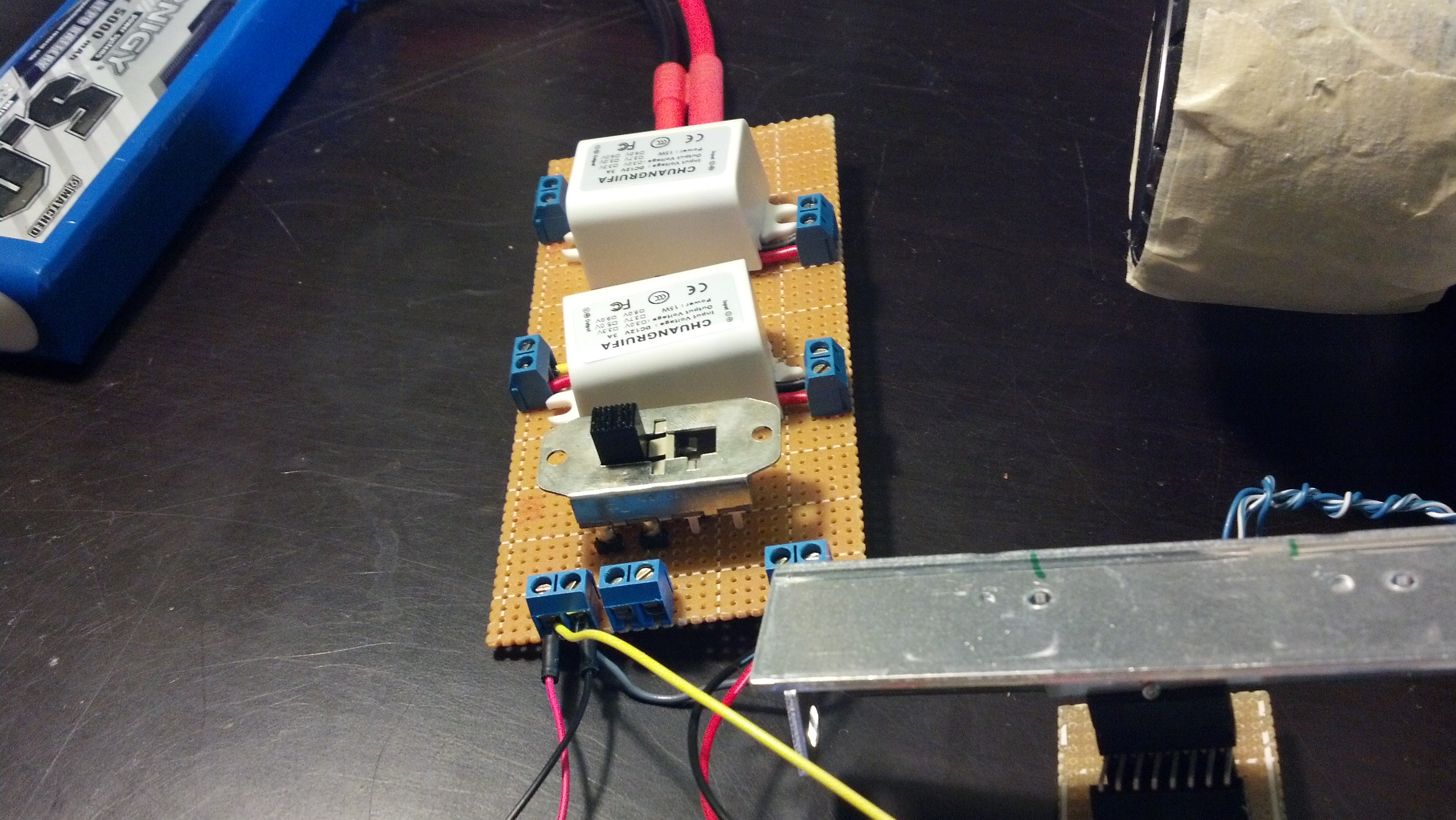
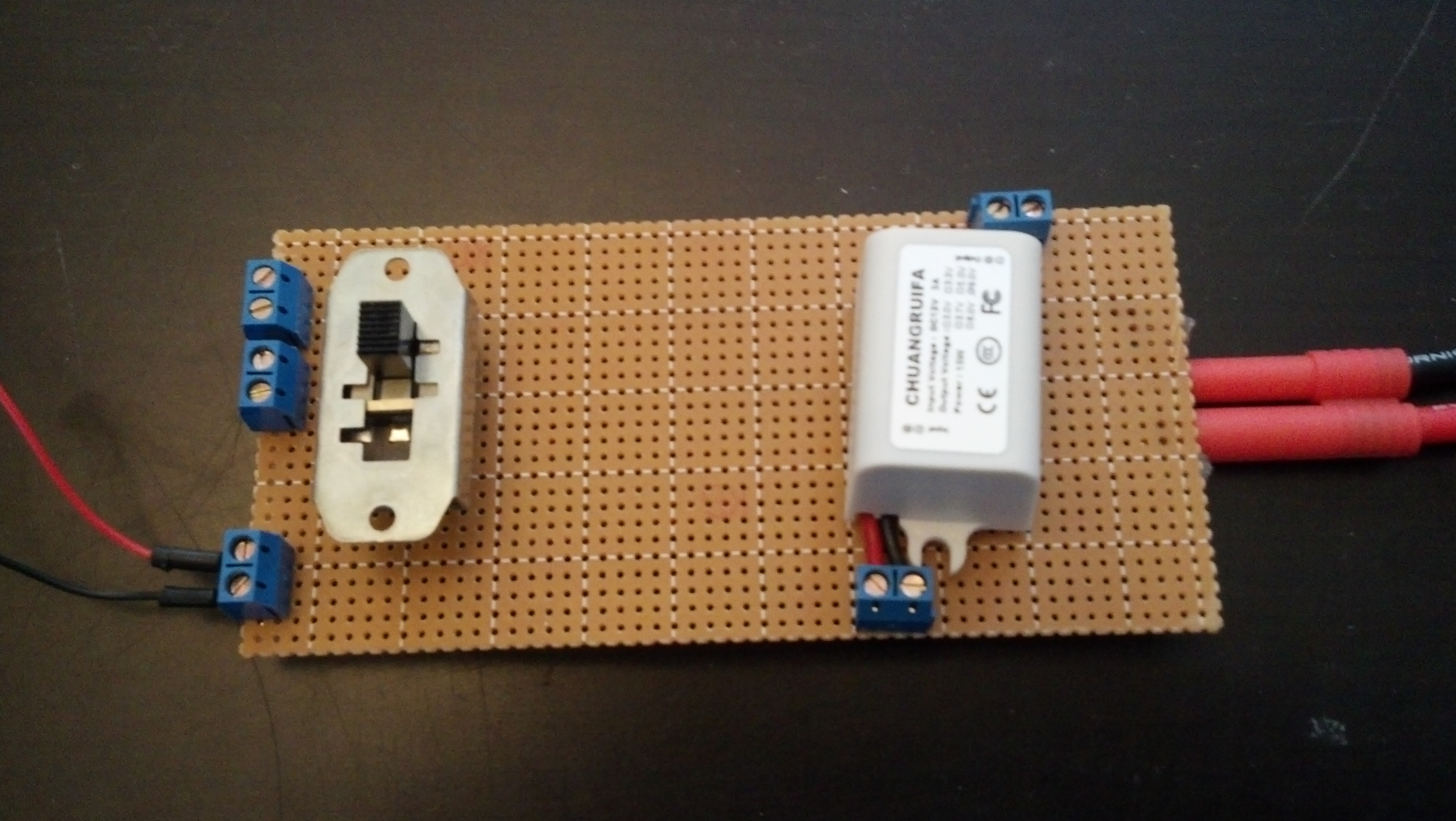
The first is the power system. At it’s core, it’s a Turnigy 5000mAh 3S 20C Lipo Battery Pack that is fed through two voltage converters. The first is 12v-9v@3A and the second is 12v-5v@3A. They are connected all via screw terminals in case they blow out. This all is fed through a large switch before it is fed into the controller and the motor driver, so it can all be cut off at a moments notice.
Here’s a video of me explaining that:
And here are some more detailed pictures:
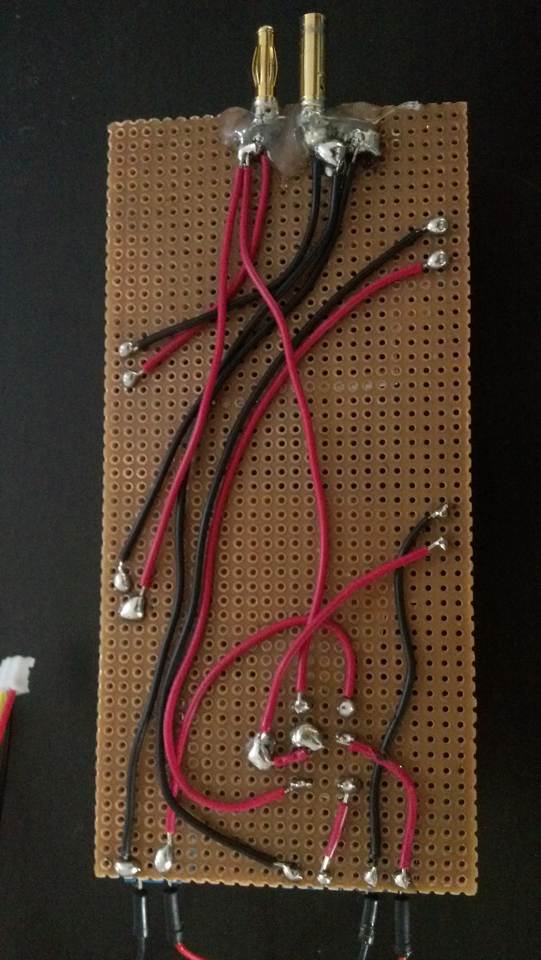
This is the bottom, I’m still not great at going from breadboard to perfboard so bear with me.

And here’s the top without the 5v module installed, but it would be exactly the same as the 9v one that is:
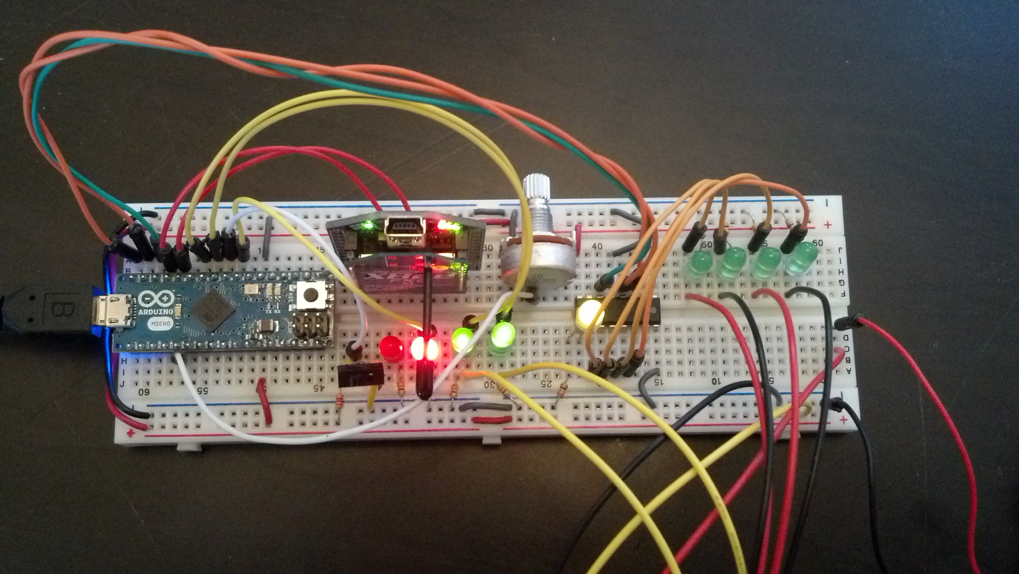
From there we go to the controller. It’s an Arduino Micro connected to a UartSBee V4 with a XBee Pro 60mW Wire Antenna – Series 1 (802.15.4) installed (the same goes for the controller). It also has a 74HC595 to free up pins which drive LED’s and the motor driver:
Here are some pictures:
Here’s the code:
|
1 2 3 4 5 6 7 8 9 10 11 12 13 14 15 16 17 18 19 20 21 22 23 24 25 26 27 28 29 30 31 32 33 34 35 36 37 38 39 40 41 42 43 44 45 46 47 48 49 50 51 52 53 54 55 56 57 58 59 60 61 62 63 64 65 66 67 68 69 70 71 72 73 74 75 76 77 78 79 80 81 82 83 84 85 86 87 88 89 90 91 92 93 94 95 96 97 98 99 100 101 102 103 104 105 106 107 108 109 110 111 112 113 114 115 116 117 118 119 120 121 122 123 124 125 126 127 128 129 130 131 132 133 134 135 136 137 138 139 140 141 142 143 144 145 146 147 148 149 150 151 152 153 154 155 156 157 158 159 160 161 162 163 164 165 166 167 168 169 170 171 172 173 174 175 176 177 178 179 180 181 182 183 184 185 186 187 188 189 190 191 192 193 194 195 196 197 198 199 200 201 202 203 204 205 206 |
//Serial Handshake declaration #include <string.h> // we'll need this for subString #define MAX_STRING_LEN 20 // like 3 lines above, change as needed. const char EOPmarker = '.'; //This is the end of packet marker char serialbuf[32]; //This gives the incoming serial some room. Change it if you want a longer incoming. //SoftwareSerial declaration #include <SoftwareSerial.h> SoftwareSerial xbee_serial(8, 9); //Shift Register Pins declaration int SER_Pin = 10; //pin 14 on the 75HC595 int RCLK_Pin = 11; //pin 12 on the 75HC595 int SRCLK_Pin = 12; //pin 11 on the 75HC595 #define number_of_74hc595s 1 //How many of the shift registers - change this #define numOfRegisterPins number_of_74hc595s * 8 //do not touch boolean registers[numOfRegisterPins]; //Servo declarations #include <Servo.h> Servo left_servo; Servo rght_servo; //Misc Pin declaration //inputs int pot = 1; int debug_switch1 = 4; //outputs int fade_LED = 3; int x_LED = 5; int y_LED = 6; //int debug_switch1_LED = 12; //Misc Integer declarations int brightness = 0; // how bright the LED is int fadeAmount = 20; // how many points to fade the LED by int x_upperTrigger = 600; int x_lowerTrigger = 400; int y_upperTrigger = 600; int y_lowerTrigger = 400; void setup(){ Serial.begin(9600); xbee_serial.begin(9600); pinMode(SER_Pin, OUTPUT); pinMode(RCLK_Pin, OUTPUT); pinMode(SRCLK_Pin, OUTPUT); pinMode(0, INPUT); clearRegisters(); writeRegisters(); pinMode(pot, INPUT); pinMode(debug_switch1, INPUT); pinMode(x_LED, OUTPUT); pinMode(y_LED, OUTPUT); pinMode(fade_LED, OUTPUT); xbee_serial.print("0,0,0."); // this is very important as it starts of the loop because it makes "xbee_serial.avalible() > 0. } void loop(){ if (xbee_serial.available() > 0) { static int bufpos = 0; char inchar = xbee_serial.read(); if (inchar != EOPmarker) { serialbuf[bufpos] = inchar; bufpos++; } else { serialbuf[bufpos] = 0; //restart the buff bufpos = 0; //restart the position of the buff handshake(); debug_handshake(); setRegisterPin(1, HIGH); writeRegisters(); } } } void handshake(){ //input, recived from controller // led1val,ledval2,fade_LEDvalue. //analogWrite(x_LED, map(atoi(subStr(serialbuf, "," , 1)),0,1023,0,255)); //analogWrite(y_LED, map(atoi(subStr(serialbuf, "," , 2)),0,1023,0,255)); analogWrite(fade_LED, atoi(subStr(serialbuf, "," , 3))); brightness = brightness + fadeAmount; // reverse the direction of the fading at the ends of the fade: if (brightness == 0 || brightness == 255) { fadeAmount = -fadeAmount ; } if (atoi(subStr(serialbuf, "," , 1)) > x_upperTrigger ){ analogWrite(x_LED, map(atoi(subStr(serialbuf, "," , 1)),512,1023,0,255)); setRegisterPin(2, HIGH); setRegisterPin(3, LOW); writeRegisters(); } if (atoi(subStr(serialbuf, "," , 1)) < x_lowerTrigger ){ analogWrite(x_LED, map(atoi(subStr(serialbuf, "," , 1)),512,0,0,255)); setRegisterPin(2, LOW); setRegisterPin(3, HIGH); writeRegisters(); } if (atoi(subStr(serialbuf, "," , 1)) > x_lowerTrigger && atoi(subStr(serialbuf, "," , 1)) < x_upperTrigger){ setRegisterPin(2, LOW); setRegisterPin(3, LOW); writeRegisters(); } if (atoi(subStr(serialbuf, "," , 2)) > y_upperTrigger ){ analogWrite(y_LED, map(atoi(subStr(serialbuf, "," , 2)),512,1023,0,255)); setRegisterPin(4, HIGH); setRegisterPin(5, LOW); writeRegisters(); } if (atoi(subStr(serialbuf, "," , 2)) < y_lowerTrigger ){ analogWrite(y_LED, map(atoi(subStr(serialbuf, "," , 2)),512,0,0,255)); setRegisterPin(4, LOW); setRegisterPin(5, HIGH); writeRegisters(); } if (atoi(subStr(serialbuf, "," , 2)) > y_lowerTrigger && atoi(subStr(serialbuf, "," , 2)) < y_upperTrigger){ setRegisterPin(4, LOW); setRegisterPin(5, LOW); writeRegisters(); } //output, sent to controller //ledpot1,fade_LEDval. xbee_serial.print(analogRead(pot)); xbee_serial.print(","); xbee_serial.print(brightness); //This second byte is for the purpose of the program, it is not being used. xbee_serial.print("."); //EOP marker delay(10); } void debug_handshake(){ //input, recived from controller Serial.print("VEHICLE DEBUG: "); Serial.print("INPUTS|"); Serial.print(" x_LED: "); Serial.print(map(atoi(subStr(serialbuf, "," , 1)),0,1023,0,255)); Serial.print(" y_LED: "); Serial.print(map(atoi(subStr(serialbuf, "," , 2)),0,1023,0,255)); Serial.print(" in fade_LED: "); Serial.print(atoi(subStr(serialbuf, "," , 3))); //output, sent to controller Serial.print(" OUTPUTS|"); Serial.print(" Pot 1: "); Serial.print(analogRead(pot)); Serial.print(" out fade_LED: "); Serial.print(brightness); Serial.println(""); } char* subStr (char* input_string, char *separator, int segment_number) { char *act, *sub, *ptr; static char copy[MAX_STRING_LEN]; int i; strcpy(copy, input_string); for (i = 1, act = copy; i <= segment_number; i++, act = NULL) { sub = strtok_r(act, separator, &ptr); if (sub == NULL) break; } return sub; } void clearRegisters(){ for(int i = numOfRegisterPins - 1; i >= 0; i--){ registers[i] = LOW; } } void writeRegisters(){ digitalWrite(RCLK_Pin, LOW); for(int i = numOfRegisterPins - 1; i >= 0; i--){ digitalWrite(SRCLK_Pin, LOW); int val = registers[i]; digitalWrite(SER_Pin, val); digitalWrite(SRCLK_Pin, HIGH); } digitalWrite(RCLK_Pin, HIGH); } //set an individual pin HIGH or LOW void setRegisterPin(int index, int value){ registers[index] = value; } |
Next is the motor driver. It’s built around the L298N. Here’s the video
Here are pictures:
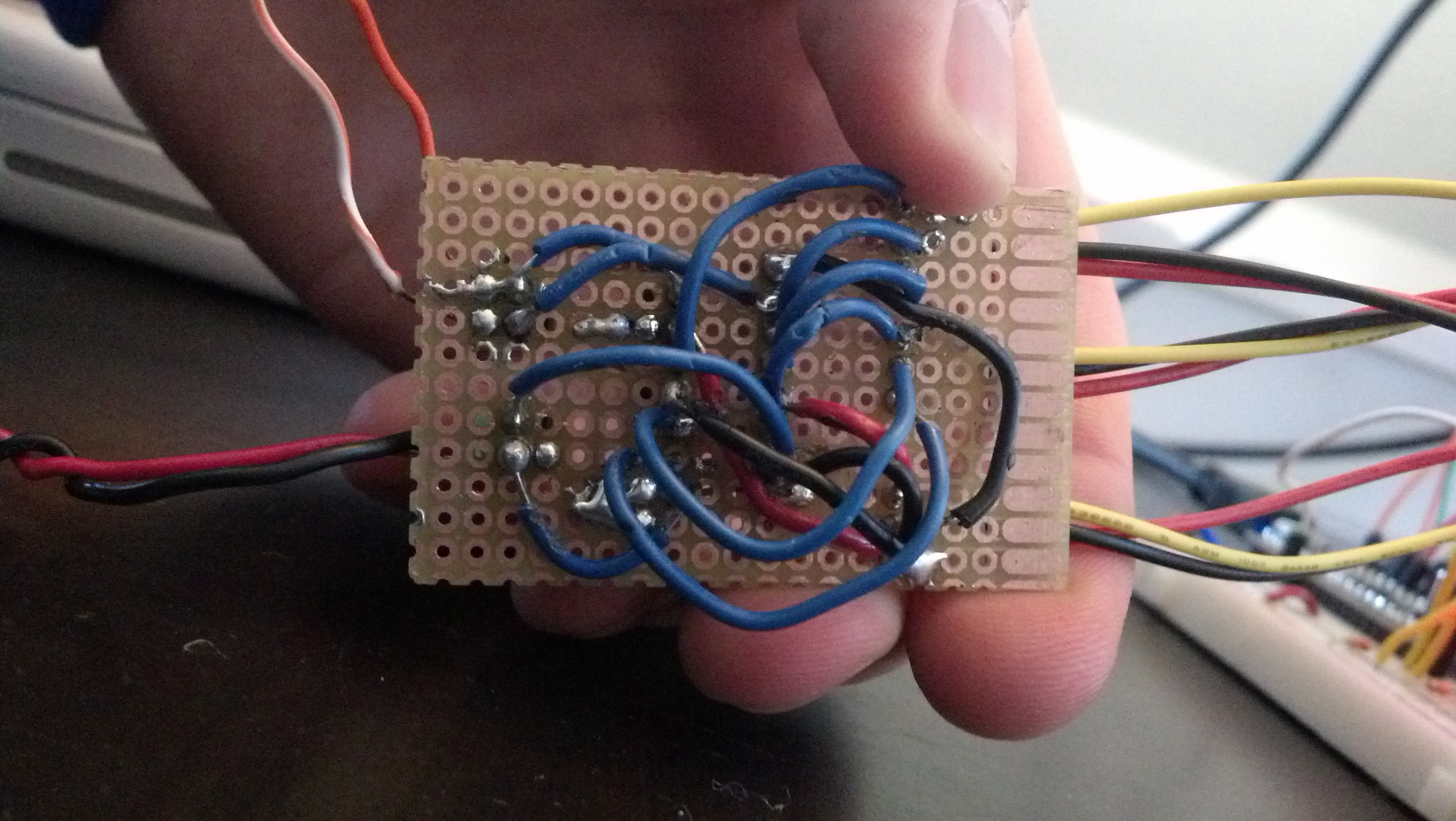

It’s my first real use of a perfboard to make a project more permanent which is why it looks awful, but this is what it should look like:
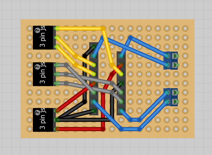
Image generated by fritzing.
The last system is the controller. It’s an arduino micro hooked up to the same xbee system as seen earlier with a joystick and a multiplexer for more inputs. Here’s a video:
And some pictures:
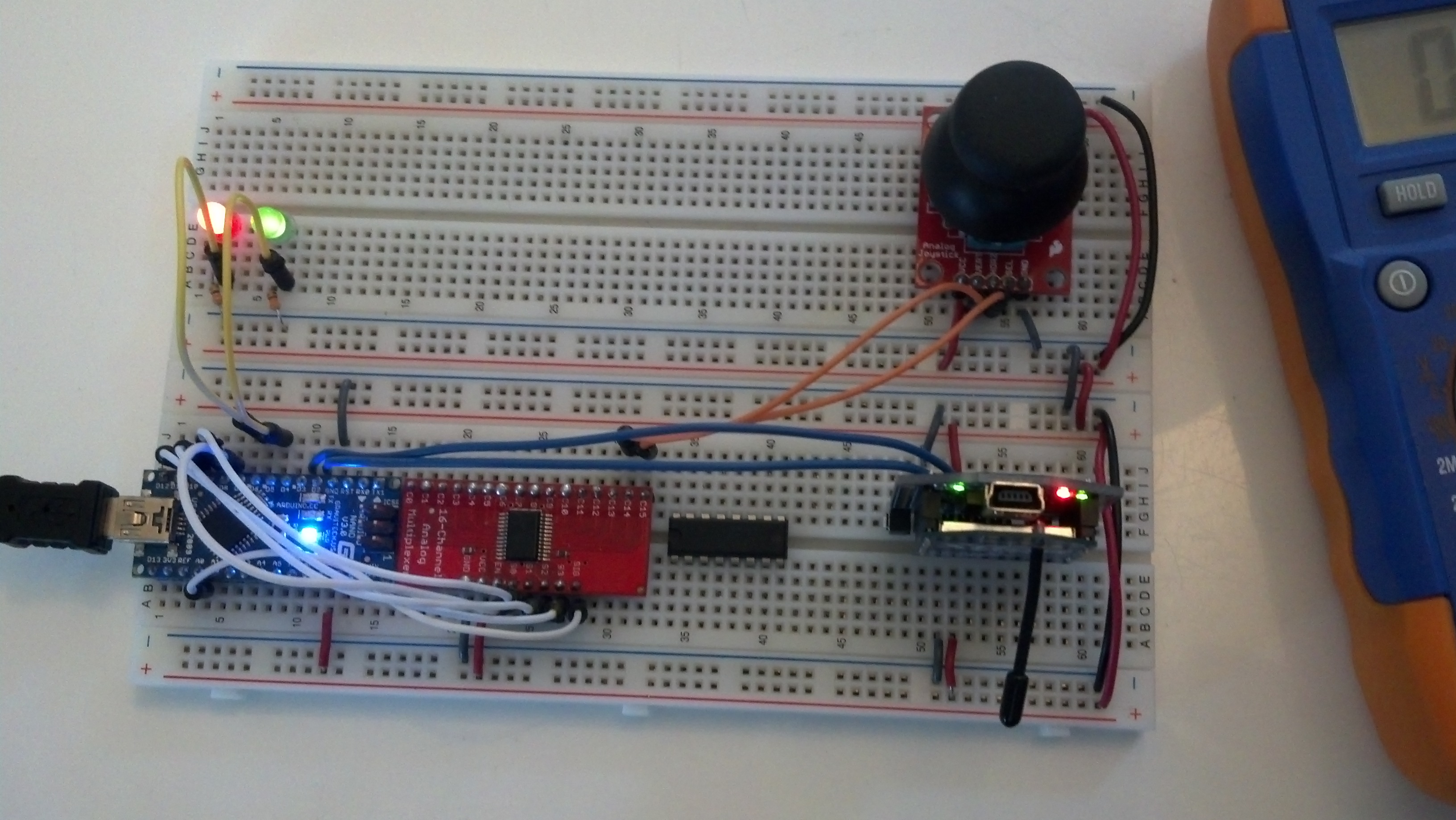
So basically it receives and sends data to and from the controller as seen in the following code:
|
1 2 3 4 5 6 7 8 9 10 11 12 13 14 15 16 17 18 19 20 21 22 23 24 25 26 27 28 29 30 31 32 33 34 35 36 37 38 39 40 41 42 43 44 45 46 47 48 49 50 51 52 53 54 55 56 57 58 59 60 61 62 63 64 65 66 67 68 69 70 71 72 73 74 75 76 77 78 79 80 81 82 83 84 85 86 87 88 89 90 91 92 93 94 95 96 97 98 99 100 101 102 103 104 105 106 107 108 109 110 111 112 113 114 115 116 117 118 119 120 121 122 123 124 125 126 127 128 129 130 131 132 133 134 135 136 137 138 139 140 141 142 143 144 145 146 147 148 149 150 151 152 153 154 155 156 157 158 159 160 161 162 163 164 165 166 167 168 169 170 171 172 173 174 175 176 177 178 179 180 181 182 183 184 185 186 187 188 189 190 191 192 |
//Serial Handshake declaration #include <string.h> // we'll need this for subString #define MAX_STRING_LEN 20 // like 3 lines above, change as needed. const char EOPmarker = '.'; //This is the end of packet marker char serialbuf[32]; //This gives the incoming serial some room. Change it if you want a longer incoming. //SoftwareSerial declaration #include <SoftwareSerial.h> SoftwareSerial xbee_serial(2, 3); //Mux control pins declarations int s0 = 8; int s1 = 9; int s2 = 10; int s3 = 11; int SIG_pin = 0; //Shift Register Pins declaration int SER_Pin = 5; //pin 14 on the 75HC595 int RCLK_Pin = 6; //pin 12 on the 75HC595 int SRCLK_Pin = 7; //pin 11 on the 75HC595 #define number_of_74hc595s 1 //How many of the shift registers - change this #define numOfRegisterPins number_of_74hc595s * 8 //do not touch boolean registers[numOfRegisterPins]; //Servo declarations int left_servo_val; int rght_servo_val; //Misc Pin declaration //inputs int debug_switch1 = 4; //outputs int pot_LED = 5; int fade_LED = 6; int debug_switch1_LED = 2; //Misc Integer Declarations int joystick_x; int joystick_y; int brightness = 0; // how bright the LED is int fadeAmount = 20; // how many points to fade the LED by void setup(){ Serial.begin(9600); xbee_serial.begin(9600); //mux setup pinMode(s0, OUTPUT); pinMode(s1, OUTPUT); pinMode(s2, OUTPUT); pinMode(s3, OUTPUT); digitalWrite(s0, LOW); digitalWrite(s1, LOW); digitalWrite(s2, LOW); digitalWrite(s3, LOW); //shift register setup pinMode(SER_Pin, OUTPUT); pinMode(RCLK_Pin, OUTPUT); pinMode(SRCLK_Pin, OUTPUT); pinMode(0, INPUT); clearRegisters(); writeRegisters(); //Misc Pin Declarations pinMode(pot_LED, OUTPUT); xbee_serial.print("0,0,0."); // this is very important as it starts of the loop because it makes "xbee_serial.avalible() > 0. } void loop(){ if (xbee_serial.available() > 0) { static int bufpos = 0; char inchar = xbee_serial.read(); if (inchar != EOPmarker) { serialbuf[bufpos] = inchar; bufpos++; } else { serialbuf[bufpos] = 0; //restart the buff bufpos = 0; //restart the position of the buff handshake(); } } } void handshake(){ //input, recived from vehicle //led1. analogWrite(pot_LED, map(atoi(subStr(serialbuf, "," , 1)),0,1023,0,255)); analogWrite(fade_LED, atoi(subStr(serialbuf, "," , 2))); brightness = brightness + fadeAmount; // reverse the direction of the fading at the ends of the fade: if (brightness == 0 || brightness == 255) { fadeAmount = -fadeAmount ; } //output, sent to vehicle //joystick1_ledval,joystick2_ledval,fade_LED. analogRemap(); xbee_serial.print(joystick_x); // Value that it sends over the serial xbee_serial.print(","); xbee_serial.print(joystick_y); //This second byte is for the purpose of the program, it is not being used. xbee_serial.print(","); xbee_serial.print(brightness); xbee_serial.print("."); //EOP marker delay(10); } void debug_handshake(){ } void analogRemap(){ joystick_x = readMux(15); joystick_y = readMux(14); } char* subStr (char* input_string, char *separator, int segment_number) { char *act, *sub, *ptr; static char copy[MAX_STRING_LEN]; int i; strcpy(copy, input_string); for (i = 1, act = copy; i <= segment_number; i++, act = NULL) { sub = strtok_r(act, separator, &ptr); if (sub == NULL) break; } return sub; } int readMux(int channel){ int controlPin[] = {s0, s1, s2, s3}; int muxChannel[16][4]={ {0,0,0,0}, //channel 0 {1,0,0,0}, //channel 1 {0,1,0,0}, //channel 2 {1,1,0,0}, //channel 3 {0,0,1,0}, //channel 4 {1,0,1,0}, //channel 5 {0,1,1,0}, //channel 6 {1,1,1,0}, //channel 7 {0,0,0,1}, //channel 8 {1,0,0,1}, //channel 9 {0,1,0,1}, //channel 10 {1,1,0,1}, //channel 11 {0,0,1,1}, //channel 12 {1,0,1,1}, //channel 13 {0,1,1,1}, //channel 14 {1,1,1,1} //channel 15 }; //loop through the 4 sig for(int i = 0; i < 4; i ++){ digitalWrite(controlPin[i], muxChannel[channel][i]); } //read the value at the SIG pin int val = analogRead(SIG_pin); //return the value return val; } void clearRegisters(){ for(int i = numOfRegisterPins - 1; i >= 0; i--){ registers[i] = LOW; } } void writeRegisters(){ digitalWrite(RCLK_Pin, LOW); for(int i = numOfRegisterPins - 1; i >= 0; i--){ digitalWrite(SRCLK_Pin, LOW); int val = registers[i]; digitalWrite(SER_Pin, val); digitalWrite(SRCLK_Pin, HIGH); } digitalWrite(RCLK_Pin, HIGH); } //set an individual pin HIGH or LOW void setRegisterPin(int index, int value){ registers[index] = value; } |
All of the parts listed in this video can be seen here which is the parts list.
That was a huge post! Thanks for reading and leave a comment if you have any questions.
Here’s a video:
|
1 |
CREATE TABLE adc_input_data_10(Sample_Number INT NOT NULL AUTO_INCREMENT PRIMARY KEY, Time VARCHAR(100), Channel_1 VARCHAR(100), Channel_2 VARCHAR(100), Channel_3 VARCHAR(100) ); |
|
1 2 3 4 5 6 7 8 9 10 11 12 13 14 15 16 17 18 19 20 21 22 23 24 25 26 27 28 29 30 31 32 33 34 35 36 37 38 39 40 41 42 43 |
#!/usr/bin/env python # -*- coding: utf-8 -*- import spidev import time import MySQLdb import sys import RPi.GPIO as GPIO import datetime now = datetime.datetime.now() pin = 26 GPIO.setmode(GPIO.BOARD) GPIO.setup(pin, GPIO.OUT) con = MySQLdb.connect('localhost','adc_user','adc_user_pass','adc_database'); cursor = con.cursor() spi = spidev.SpiDev() spi.open(0, 0) maxcyclenumber = 10 count = 0 def readadc(adcnum): # read SPI data from MCP3008 chip, 8 possible adc's (0 thru 7) if adcnum > 7 or adcnum < 0: return -1 r = spi.xfer2([1, 8 + adcnum << 4, 0]) adcout = ((r[1] & 3) << 8) + r[2] return adcout for _ in range(maxcyclenumber): cursor.execute("INSERT INTO adc_input_data_10(Time,Channel_1,Channel_2,Channel_3) VALUES(%s,'%s','%s','%s')",(datetime.datetime.now().strftime('%b-%d-%I%M%p-%G'),readadc(0),readadc(1),readadc(2)) ) con.commit() #this is important for live updating count = count+1 print count time.sleep (1) if count == maxcyclenumber: GPIO.cleanup() con.close()</pre> |
|
1 2 3 4 5 6 7 8 9 10 11 12 13 14 15 16 17 18 19 20 21 22 23 24 25 26 27 28 |
<?php mysql_connect("localhost", "adc_user","adc_user_pass") or die ("Could not connect: " . mysql_error()); mysql_select_db("adc_database"); $result = mysql_query("SELECT * FROM adc_input_data_10"); echo "<table border='1'> <tr> <th>Sample Number</th> <th>Time</th> <th>Channel 1</th> <th>Channel 2</th> <th>Channel 3</th> </tr>"; while($row = mysql_fetch_array($result)){ echo"<tr>"; echo"<td>" . $row['Sample_Number'] . "</td>"; echo"<td>" . $row['Time'] . "</td>"; echo"<td>" . $row['Channel_1'] . "</td>"; echo"<td>" . $row['Channel_2'] . "</td>"; echo"<td>" . $row['Channel_3'] . "</td>"; echo"</tr>"; } echo "</table>"; mysql_close($con); ?> |