I recently wrote a piece of software for a friend working on a project, you can find it on github here. The following is from the README.md:
zipcode-distance-excel
This is a command line utility to automatically calculate the distance between two zipcodes and then put the results in an excel (.xlsx) file. It works for US postal codes only.
It was developed to help a colleague and is very application-specific.
Prerequisites
Downloading is easy git, which is already on most systems, on ubuntu use:
A step by step series of examples that tell you have to get a development env running
Say what the step will be
git clone https://github.com/esologic/zipcode-distance-excel
cd zipcode-distance-excel
python3 setup.py install
Usage
in a directory with the .xlsx file that you want to modify, run:
python3 zde.py
The program skips the first row in the spreadsheet to avoid headers.
Example Usage
Before:
Terminal output:
Which file would you like to modify?
[0] - International Addresses.xlsx
[1] - testbook.xlsx
File Number: 1
You've selected [testbook.xlsx] to edit.
Which sheet would you like to modify?
[0] - Sheet1
[1] - Sheet2
[2] - Sheet3
Sheet Number: 0
You've selected [Sheet1] to edit.
Which column to read? (ie. A, B, AA): A
Which column to write result? (ie. A, B, AA): B
Point A Zipcode? 02114
Job Complete. 10 modifications made.
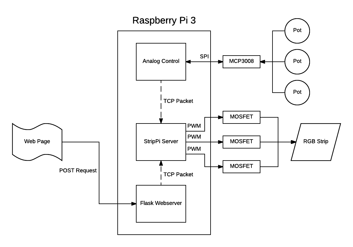
I’m constantly loosing the remote for my RGB LED strip lights, and I have a few days for spring break, time to get hacking. Here’s a demo and explanation video:
I don’t mention it in the video, but the cool part of this project is how the different processes communicate with each other. Rather than interacting with the different processes through pipes, or something like stdin, I’ve decided to use a TCP websocket server:
Processes on the device send RGB values to the Strip Server via a TCP packet. This very very easy to implement, and almost all of the hard work is taken care of via the socketserver module included in python3. This also allows for interactions with that main process (the StripPi Server process) to take place off of the Raspberry Pi as well. I plan on writing an Alexa integration for this project moving forward, and this should make that a lot easier.
The analog to digital conversion is handled by an MCP3008, exactly the same way as I did it here.
Trying to get the most out of a day has been big theme of my life lately, as I’m sure it is for many people. I’ve found that I always manage my time better when things are urgent; I’m considerably more productive when I have to be.
I want an ascetically pleasing way to be able to represent how much time is left in the day at a granular scale, like an hourglass. Watching individual seconds disappear will look cool and (hopefully) create that sense of urgency that I want to induce.
Technically, this is a really simple thing to accomplish thanks to python and pygame. Here’s a video of a proof of concept running on my laptop:
At the start of each day, the display is filled with squares at random locations, with a random color. As each second elapses, a square will vanish.
To make it easier to see for the video, I’ve made the squares much bigger than they will actually be for the final build. This is what the display looks like with the squares at their actual size:
The code really really simple, like less than 100 lines simple. Here’s how it works:
Here’s the version of the code running on my computer in the video:
import pygame
from random import randint
from apscheduler.schedulers.blocking import BlockingScheduler
import datetime

class random_square(object):
    def __init__(self, max_x_location, max_y_location):

        self.x_loc = randint(0, max_x_location)
        self.y_loc = randint(0, max_y_location)

        max_color_value = 255

        red = randint(0, max_color_value)
        green = randint(0, max_color_value)
        blue = randint(0, max_color_value)

        self.color = [red, green, blue]


class clock(object):
    def __init__(self, initial_count, max_count, screen_w, screen_h):

        self.max_count = max_count
        self.screen_w = screen_w
        self.screen_h = screen_h

        # create the screen object, force pygame fullscreen mode
        self.screen = pygame.display.set_mode([screen_w, screen_h], pygame.FULLSCREEN)

        # the screen's width in pixels is stored in the 0th element of the array
        self.square_size = screen_w / 200

        # create the list of squares, initially as empty
        self.squares = []

        # fill the squares with the inital seconds until midnight
        for second in range(initial_count):
            self.squares.append(random_square(screen_w, screen_h))


    # starts ticking the clock
    def start(self):
        scheduler = BlockingScheduler()
        scheduler.add_job(self.tick, 'interval', seconds=1)
        try:
            scheduler.start()
        except (KeyboardInterrupt, SystemExit):
            pass

    # this occurs once every time a unit of time elapses
    def tick(self):
        # this will happen once per "day"
        if len(self.squares) == 0:

            # fill the list of squares to be drawn
            for second in range(self.max_count):
                self.squares.append(random_square(self.screen_w, self.screen_h))

        # draw a blank screen
        self.screen.fill([0, 0, 0])

        # draw the squares
        for square in self.squares:
            rect = (square.x_loc, square.y_loc, self.square_size, self.square_size)
            pygame.draw.rect(self.screen, square.color, rect, 0)

        pygame.display.update()

        # remove a single square from the list as one tick has elapsed
        self.squares.pop()

# initialize pygame
pygame.init()

# figure out the parameters of the display we're connected to
screen_width = pygame.display.Info().current_w
screen_height = pygame.display.Info().current_h
screen_size = screen_width, screen_height

# determine the number of seconds until midnight
seconds_in_a_day = 86400
now = datetime.datetime.now()
midnight = now.replace(hour=0, minute=0, second=0, microsecond=0)
seconds_until_midnight = seconds_in_a_day - (now - midnight).seconds

# create and start the clock!
cl = clock(seconds_until_midnight, seconds_in_a_day, screen_width, screen_height)
cl.start()
Let’s walk through some of the design decisions of this code. The first thing that’s worth talking about is how the data for the squares is handled:
class random_square(object):
    def __init__(self, max_x_location, max_y_location):

        self.x_loc = randint(0, max_x_location)
        self.y_loc = randint(0, max_y_location)

        max_color_value = 255

        red = randint(0, max_color_value)
        green = randint(0, max_color_value)
        blue = randint(0, max_color_value)

        self.color = [red, green, blue]
It’s just an object with no methods, and on initialization, all the parameters of the square (location and color) are generated randomly as opposed to just floating the raw numbers in arrays around (even though that’s basically what is happening). This let’s us fill the squares array very easily later on in the file here:
# fill the squares with the inital seconds until midnight
for second in range(initial_count):
    self.squares.append(random_square(screen_w, screen_h))
and here:
# this will happen once per "day"
if len(self.squares) == 0:

    # fill the list of squares to be drawn
    for second in range(self.max_count):
        self.squares.append(random_square(self.screen_w, self.screen_h))
When it comes time to draw these squares, it also makes that pretty intuitive:
# draw the squares
for square in self.squares:
    rect = (square.x_loc, square.y_loc, self.square_size, self.square_size)
    pygame.draw.rect(self.screen, square.color, rect, 0)
Again, very simple stuff, but worth it to talk about.
I’ll be back at my place that has the Raspberry Pi and display I would like to use for this project, so more on this then.
So I’ve been working a lot in the past day in ironing out part of the night side loop (loop 3 in this diagram). Basically, it starts recording based on an input from a sensor and continues to record until these inputs stop occurring.
My test code looks like this
v1 = CameraModuleVideo("/home/pi/CreatureCapture/", "video1")

try:
	v1.startRecording()
except ValueError as e:
	print(e)

FilmDurationTrigger(5)

try:
	v1.stopRecording()
except ValueError as e:
	print(e)
The interesting functions at work here are the following:
def FilmDurationTrigger(time):
	t = CameraTimer(time)

	while True:
		continueFlag = False
		print "Filming For " + str(time) + " Seconds"
		t.run()
		while (t.isExpired() != True):
			if (GetContinueTrigger() == True):
				continueFlag = True
				print "Trigger Found, Continuing"
		print "Time Has Expired, Continue Flag Is Set To " + str(continueFlag)
		if (continueFlag == False):
			break
FilmDurationTrigger() Takes the period of time that will be filmed, in this example, it’s 5 seconds just to conserve time, but in application it will be 20 seconds. This code will pause for the input time, and continue to be paused upon inputs from GetContinueTrigger(). This delay allows the code to continue filming until there are no inputs.
In this example, GetContinueTrigger() returns a Boolean if a random event occurs, but in application it will return a Boolean based on the status of a motion detector.
def GetContinueTrigger():
	z = randint(0,10000)
	k = ((z == 115))
	return k
I ran two tests, both of them produced separate results. The first one created a 10 second long video:
pi@raspberrypi ~/CreatureCapture $ python CreatureCaptureTest2.py
Filming For 5 Seconds
Trigger Found, Continuing
Time Has Expired, Continue Flag Is Set To True
Filming For 5 Seconds
Time Has Expired, Continue Flag Is Set To False
Terminated
And the second created a 15 second long video:
pi@raspberrypi ~/CreatureCapture $ python CreatureCaptureTest2.py
Filming For 5 Seconds
Trigger Found, Continuing
Trigger Found, Continuing
Trigger Found, Continuing
Trigger Found, Continuing
Time Has Expired, Continue Flag Is Set To True
Filming For 5 Seconds
Trigger Found, Continuing
Time Has Expired, Continue Flag Is Set To True
Filming For 5 Seconds
Time Has Expired, Continue Flag Is Set To False
Terminated
These two test shows that variable capture length functionality works! As a note, the actual times on the output video varies from the amount of time that it’s designed to record for. This is because the variable frame rate nature of the video coming out of the camera module, it causes the videos to come out a little short, but they still contain all the frames of the amount of time desired to record, just scaled slightly by frame rate error.
One of the biggest problems with the built in commands for using the Raspberry Pi Camera module is that you can’t stop a recording after an unknown time. You can record for a given number of seconds and that’s it. I have attempted to solve this problem by backgrounding the initial record process with a time of 27777.8 hours (99999999 seconds) when it’s time to stop recording, the process is manually killed using pkill.
Here is a test of my code, which I’ve called CameraModulePlus (written in python) which takes two videos, one for five seconds, and one for ten seconds, with a 10 second delay in between.
from CameraModulePlus import CameraModuleVideo
import subprocess
from time import sleep
import time

v1 = CameraModuleVideo("/home/pi/CreatureCapture/", "video1")
v2 = CameraModuleVideo("/home/pi/CreatureCapture/", "video2")

try:
	v1.startRecording()
	time.sleep(5)
	v1.stopRecording()

	time.sleep(10)

	v2.startRecording()
	time.sleep(10)
	v2.stopRecording()

except ValueError as e:
	print(e)
Here is a result of the 5 second duration test:
Here is a result of the 10 second duration test:
As you can see, it works pretty good for how barbaric it is. The full class for CameraModuleVideo can be found here. In the future, I’d like to encode a lot more data into the CameraModuleVideo class, things about time etc. Also I would like to monitor available space on the device to make sure there is enough space to record.
I’ve decided to embark on a video surveillance project! My family lives in a very rural part of the US, and constantly hear and see evidence of animals going crazy outside of my home at night. The goal of this project is to hopefully provide some kind of insight as to what animals actually live in my backyard.
Ideally, I want to monitor the yard using some kind if infrared motion detector. Upon a motion detection, an IR camera assisted by some IR spotlights would begin filming until it has been determined that there isn’t any more movement going on in yard. These clips would then be filed into a directory, and at the end of the night, they would be compiled and uploaded to YouTube. This video would then be sent to the user via email.
I’ve created the following flowchart to develop against as I begin implementing this idea.
I’ll be using a Raspberry Pi to implement this idea, a few months back I bought the IR camera module and haven’t used it for anything, this would be a good project to test it out.
There are a few hurtles that I’ll have to cross in order to make this project a success, like most groups of problems I deal with, they can be separated into hardware and software components.
Hardware
Minimize false positives by strategically arranging motion detectors
Make sure IR Spotlights are powerful enough to illuminate area
Enclosure must be weatherproof & blend in with environment, Maine winters are brutal.
Software
The Pi doesn’t have any built in software to take undetermined lengths of video.
Must have a lot of error catching and other good OO concepts in order to ensure a long runtime.
I’ve actually come up with a routine for solving the first software problem I’ve listed, hopefully I’ll have an example of my solution in action later tonight.
Ideally, this project will have a working implementation completed by May 21, which is 7 days from now.
First here’s a video of me demonstrating a few of the new features:
So compared to the original version of this project, the following changes are as follows:
Added function that takes image from incoming tweet, finds most common color in the image and writes it to the LEDs.
Added fading between colors instead of just jumping between them.
Added routine to respond to users when an error occurs in their tweet, like it’s missing a color or something is spelled wrong.
Re-Wrote most of code into an objects and methods on that object to get rid of global variables.
A few notes on the new features:
The operation of the image ingestion feature is pretty simple. All you have to do is tweet an image at @heyWPI just like you would with text. It finds the most common color in the image and then writes it the the LEDs. Here’s an example:
It works pretty well. If you look at the code, you’ll see that I tried to make it as modular as I could so I can possibly improve the color detection algorithm moving forward without making major changes in the code. This required the system to have some kind of memory to keep track of the current values written to the LEDs. Originally, I was using global variables to solve this problem but it wasn’t all that clean so I made it all more object oriented.
As for the fading You can sort of see it in the video, but the fading between colors looks really nice, especially from and to opposite complex colors like purple to orange.
A big problem I had with different people using the project was that sometimes people would use an invalid color. I implemented a default message to send if a received tweet didn’t have a color in the text or didn’t have an image in the body.
You should be ready to rock and roll on the software side, now let’s look at the hardware schematic.
I’ve tried to make this as simple as possible, but it probably isn’t the best way to drive these LEDs, moving forward I’d like to drive these strips with a constant current.
Using the python library, tweepy, getting the twitter interaction to work was actually very simple. The downside is that I can only retrieve mention data every 60 seconds due to Twitter’s API rate limiting.
The circuit is very simple, the RGB led strip I have is common anode, so I used N-Channel mosfets attached to pins 18 (Red), 23 (Green) and 24 (Blue). For the camera, I’m using a spare raspberry pi camera module I have.
For the names of the colors you can write to the lights, I went with the 140 X-11 colors. I figured it was a good spectrum of colors.
I’d love to expand the scale of the project, if you’re a student at wpi and would like on of these in your window, please email me at the addressed listed in the about section of my website.