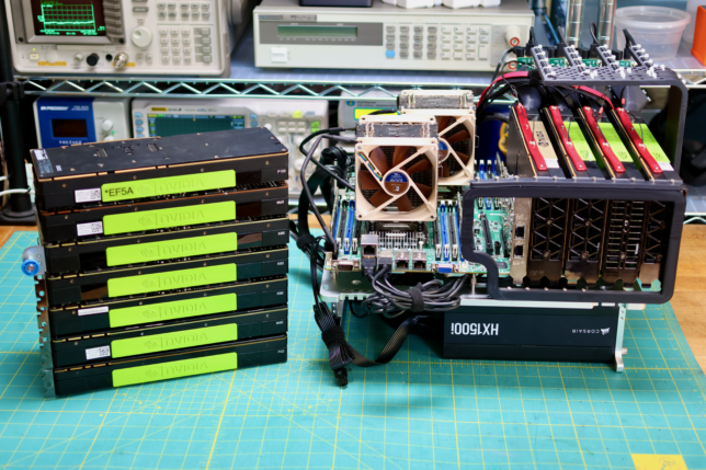
Previously a plan was set in motion to benchmark my collection of mighty Tesla GPUs. The set of cooler manifolds are designed, a GPU server benchmark suite has been created, and the time has come to start working through the spreadsheet. I have long suspected that the older multi node cards could be fantastic for image processing. Finally we can quantify how much life is left in these older cards.
In the years since the GANce days, Rosewill’s massive 4U chassis, RSV-L4000U has housed my daily-driver virtualization host. The guts of the build are almost identical to the original spec, but it has come time to move into a smaller case. CX4200A from Sliger won out because of a few factors.
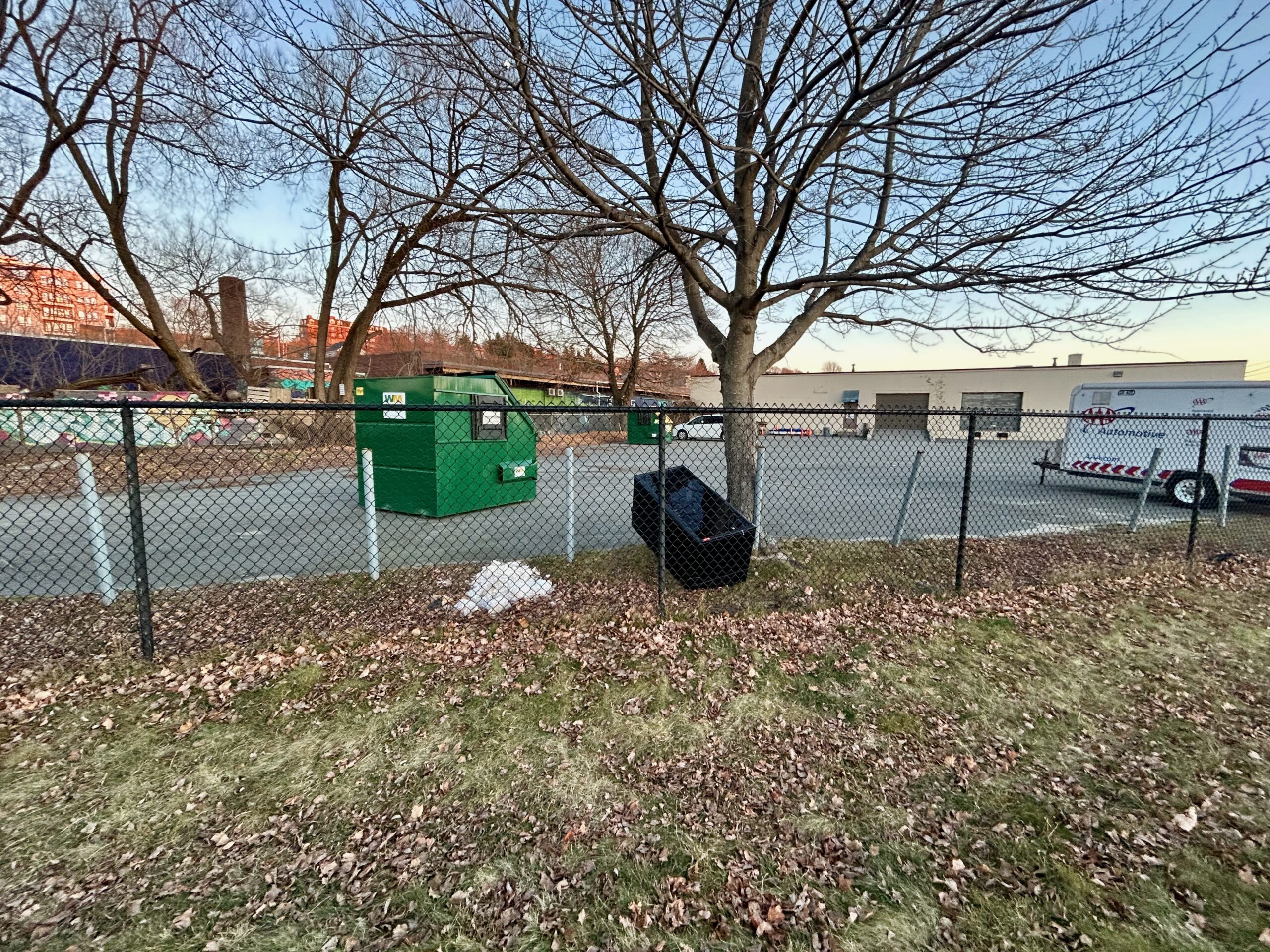
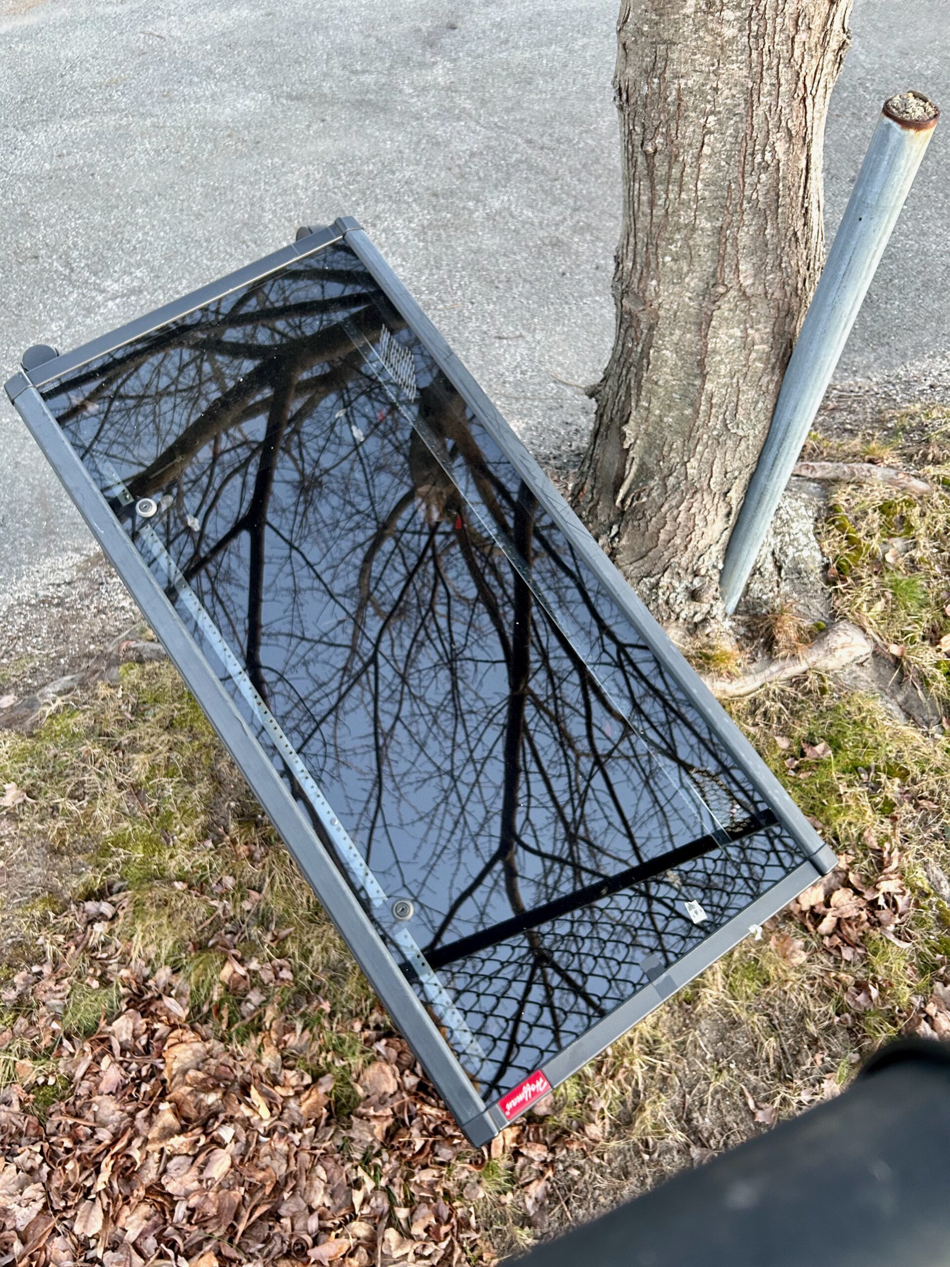
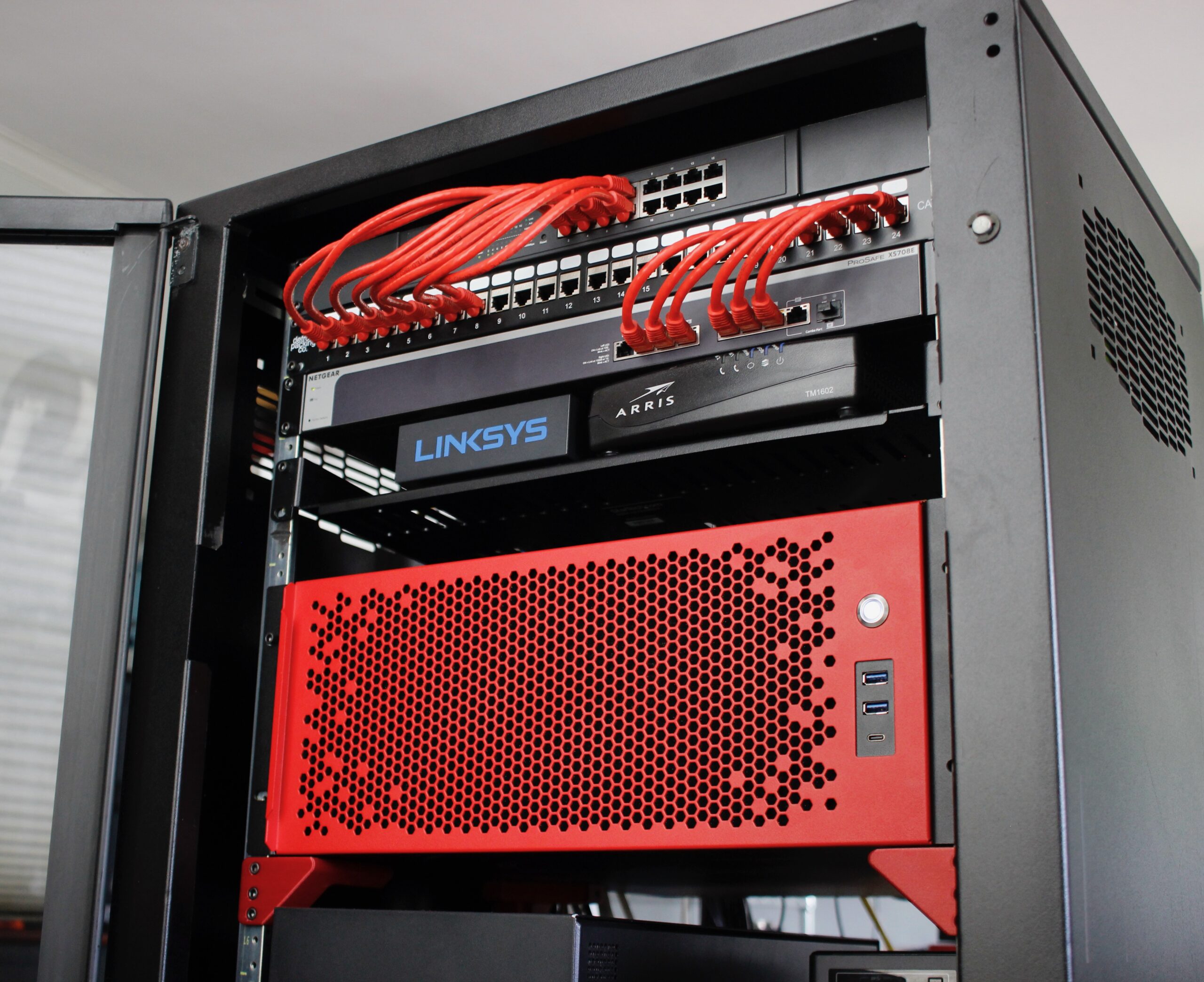
The main one is that, following some flooding in my city, someone discarded a Hoffman EWMW482425 26U short-depth rack with a flawless glass door and an MSRP over over $1000:
Before…
Original Discovery.
Fits in the S-10.
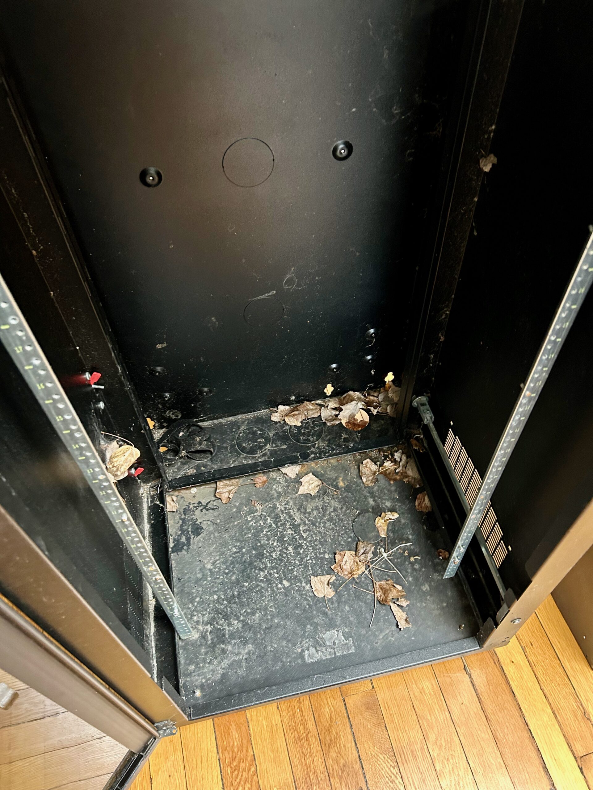
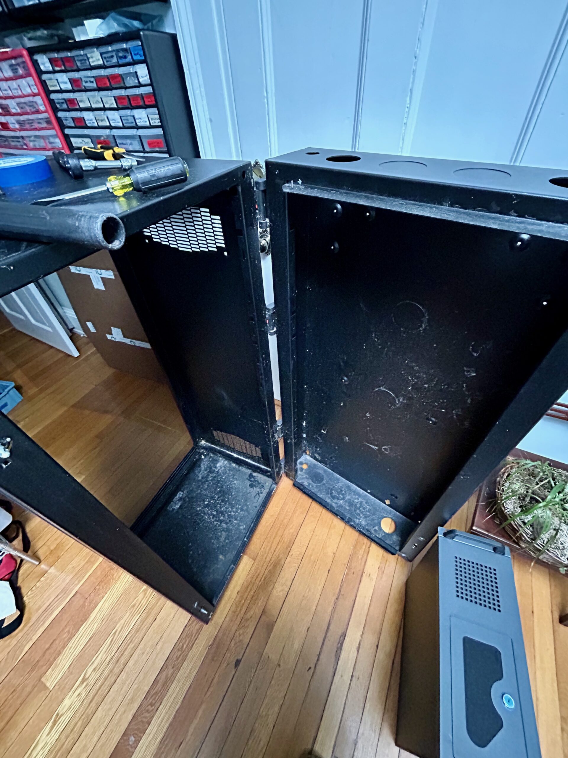
Dirt and grime.
Dirt and grime.
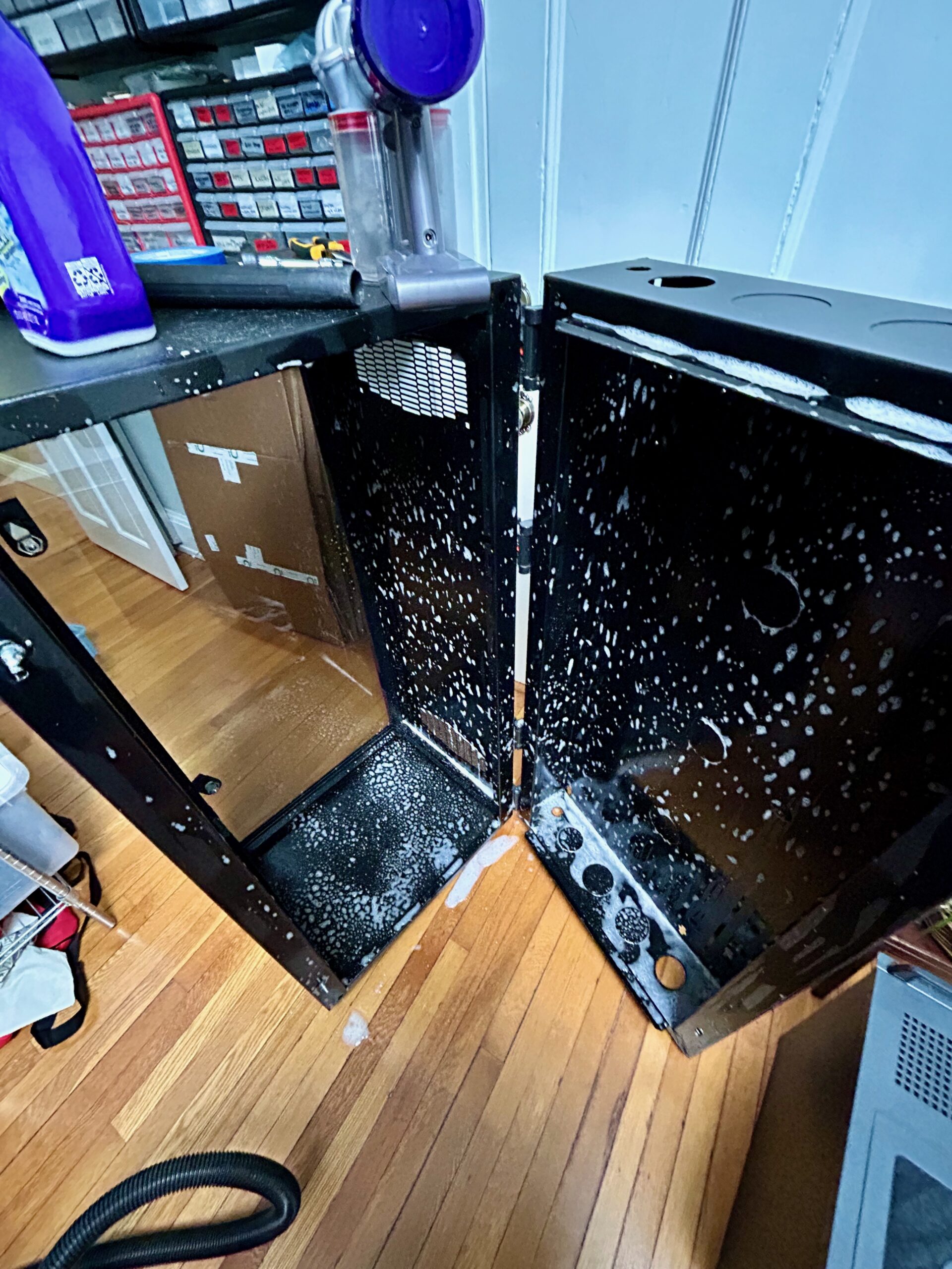
Cleaning.
After! CX4200A is the big red one.
Under the cover of darkness, a co-conspirator and I were able to heist the rack from its resting place back to mine.
Judging by the bits left in inside, it looks to have served as a housing for telecom gear. Much of the rackable gear I’ve come into over the years is similarly short-depth with one exception, the Rosewill.
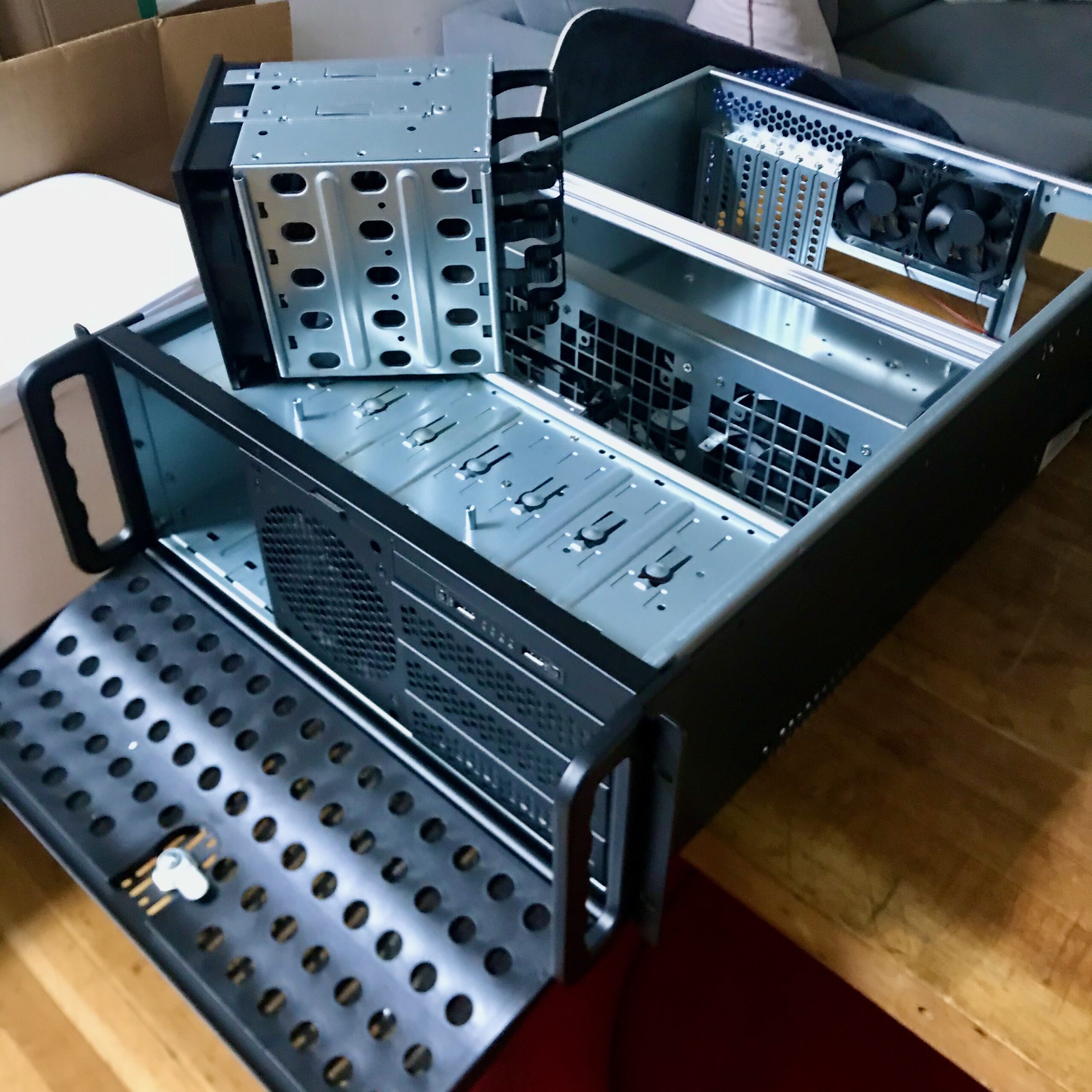
Freshly unboxed.
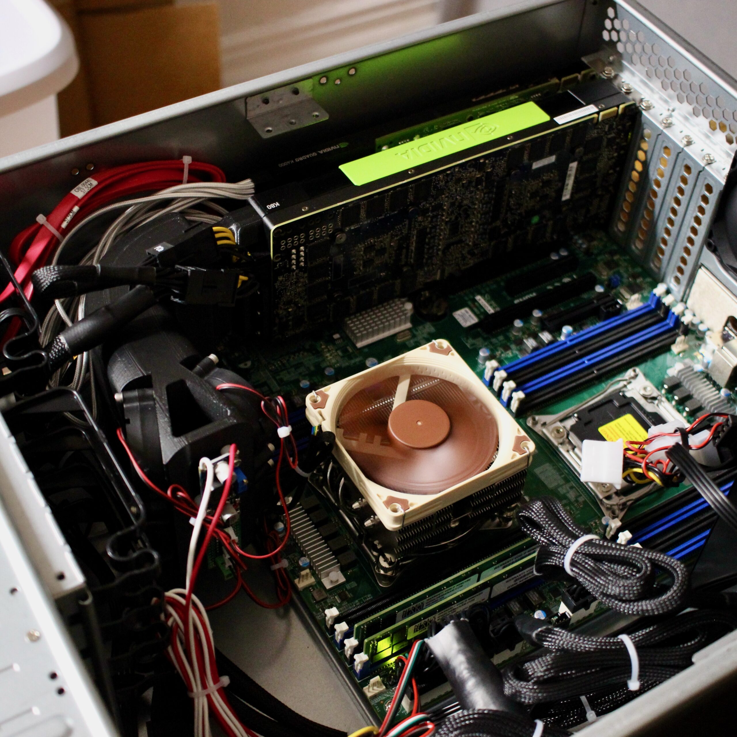
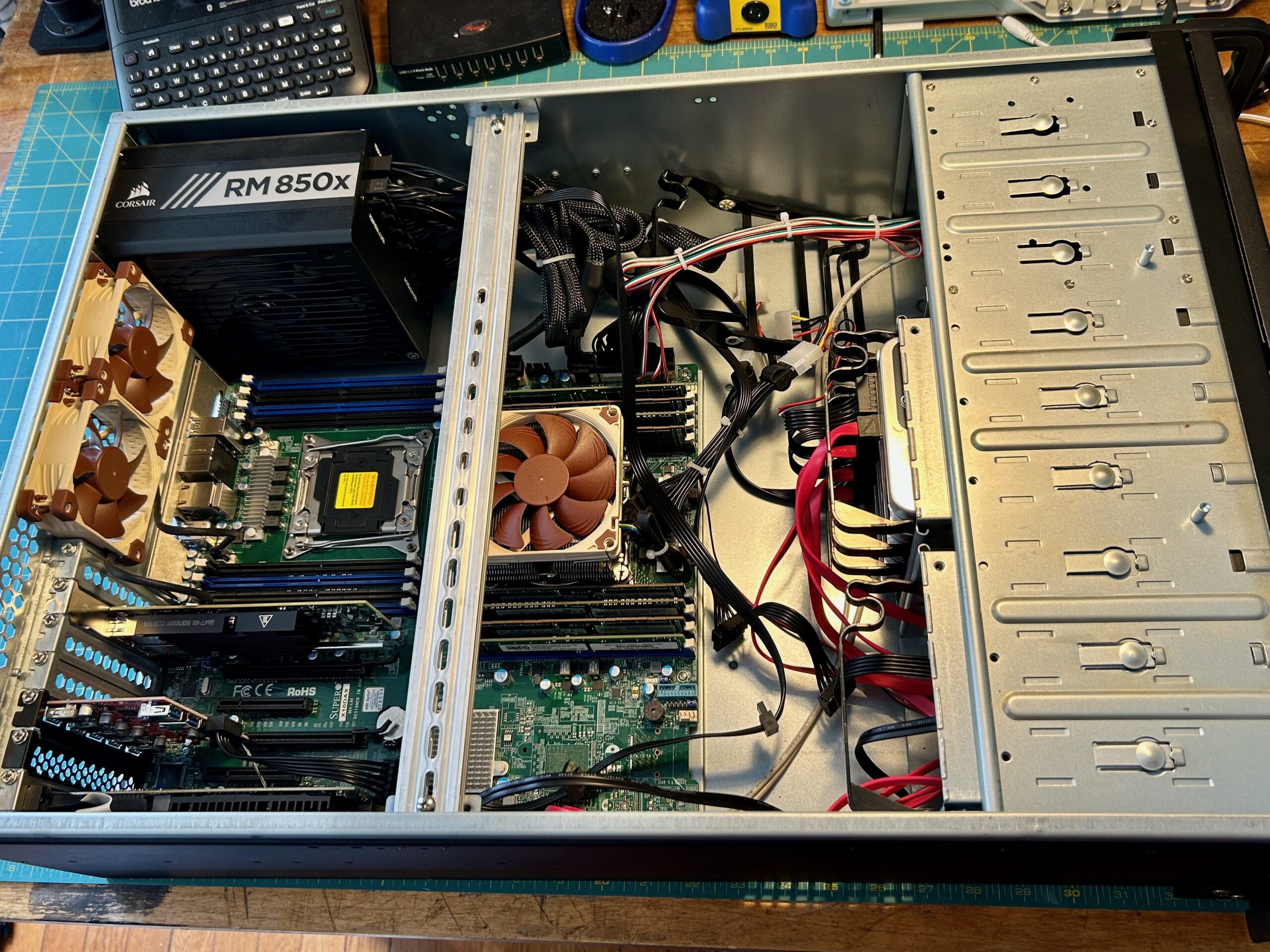
Big cooler fit no problem.
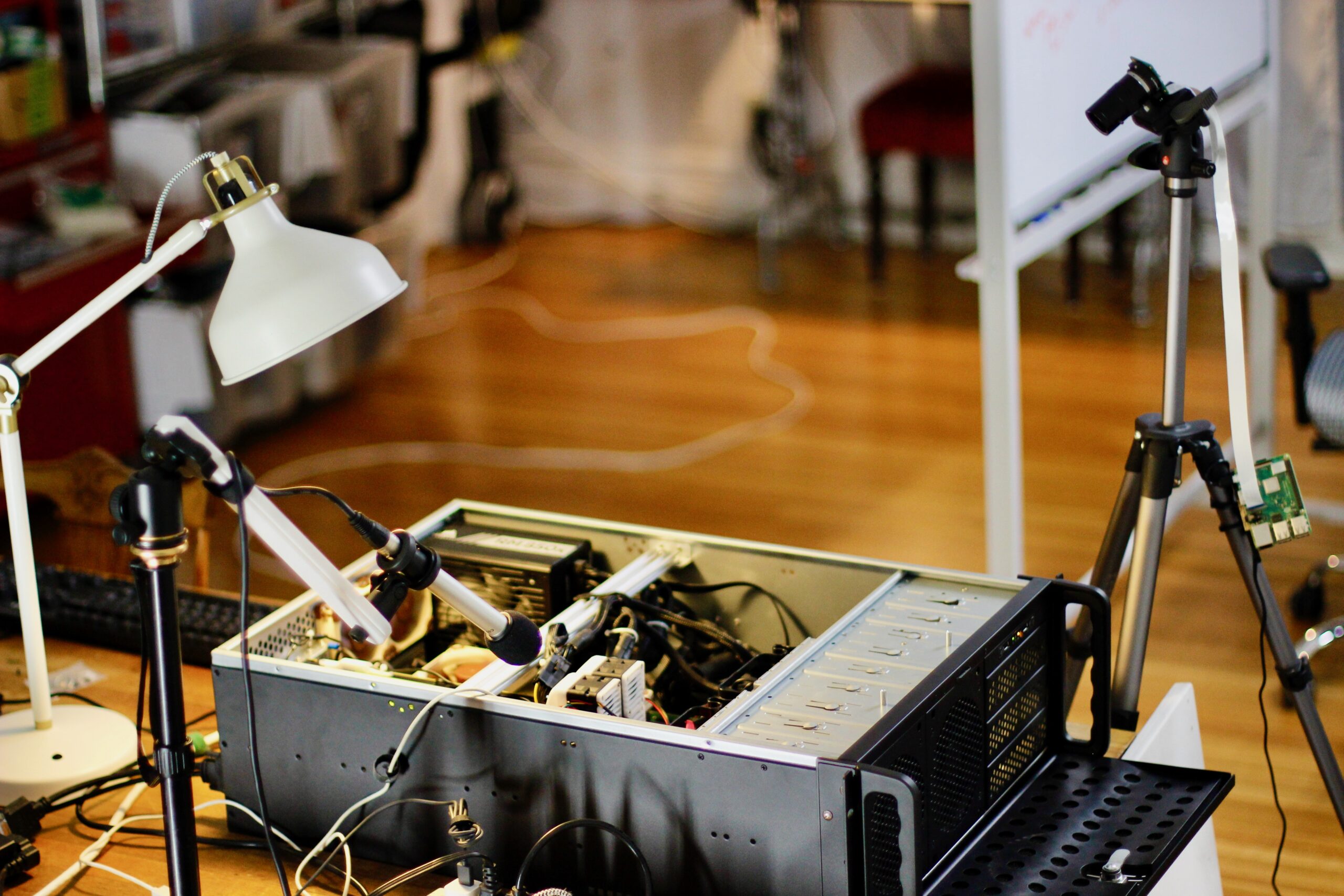
Recording For Tesla Cooler Livestreams
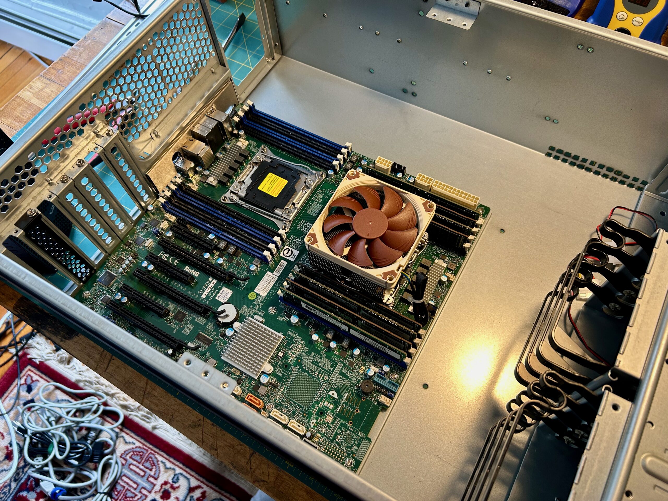
Motherboard only, so much space.
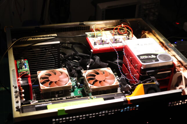
Final config before migrating the system to the sliger chassis.
The 25″ of depth is way too much for the rack. It was great for being able to work on tesla cooler, plenty of room for weird coolers and hard drives. The weight, the physical mass of the thing is also just too much. I’ve moved apartments twice since acquiring the Rosewill and have dreaded moving it both times. These aren’t RSV-L4000U’s fault, these are features for the majority of users. Just not for me right now.
Enter the Sliger CX4200A and a few modifications to make it perfect for my needs:
There’s a triple-point energy to working on something out at the edge of your abilities. Enumerated alongside the possibilities for failure are visions of the finished piece, installed and gloriously humming along, that make the long nights ahead less intimidating.
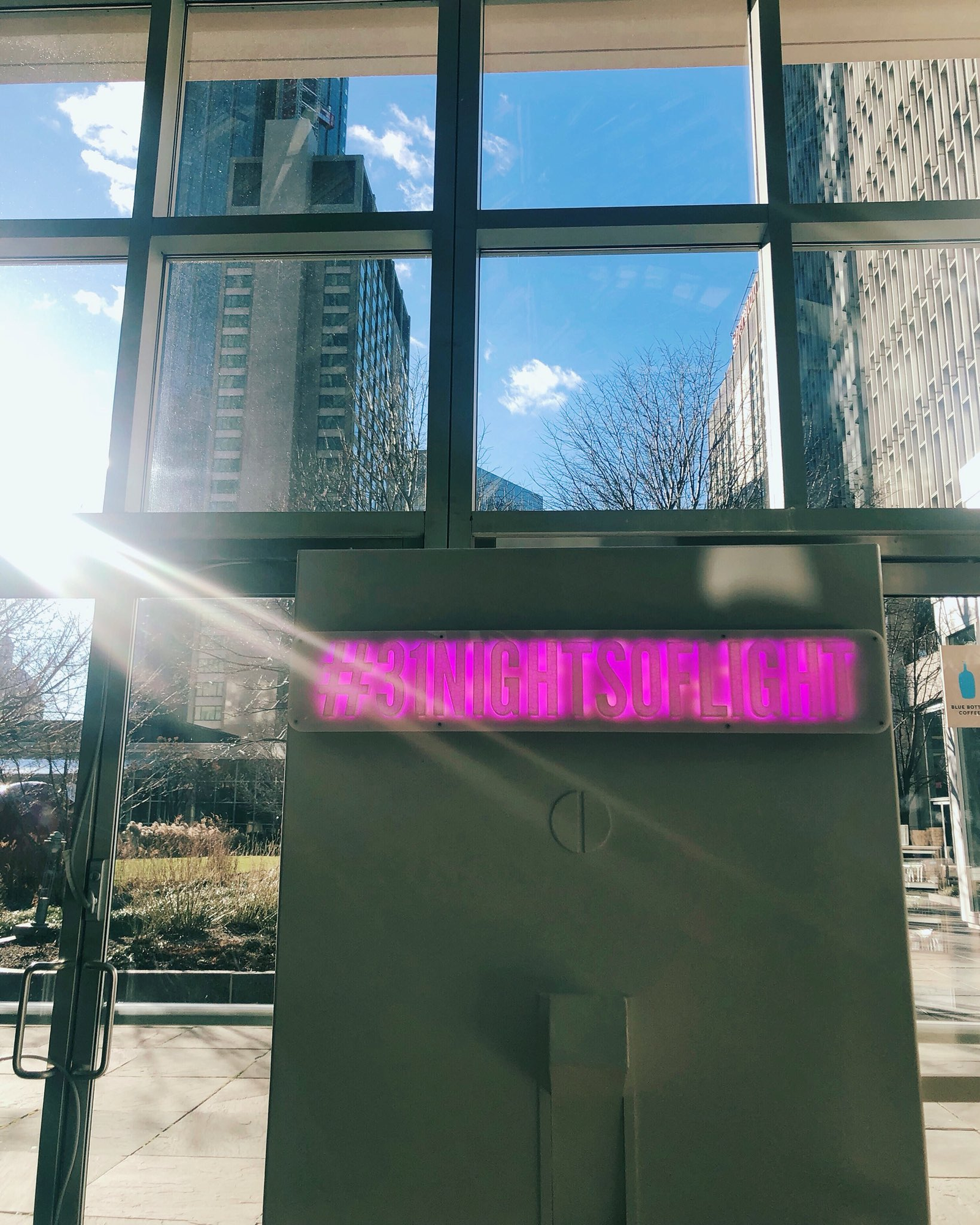
In late October of 2018, I began the CAD for such a project. Telapush had just closed our largest deal to date. We were to contracted to build a massive illuminated sign that would map social media interactions to custom animations to be displayed in real time. The piece was to run, un-attended for the entire month of December in the Center Court of the Prudential Center mall, inside of Boston’s most distinctive skyscraper.
Erin and I had been pouring effort into Telapush for some time, and this installation was to be the largest tangible result from that effort. Serious people spending real money and expecting actual results. Boston was my new home and I felt that this project was my chance to make a good first impression to this new and intimidating place. This heightened importance, paired with the reverence for the challenge, coaxed out some good engineering; the project was a rousing success. More details about this installation can be found in my portfolio entry on the project.
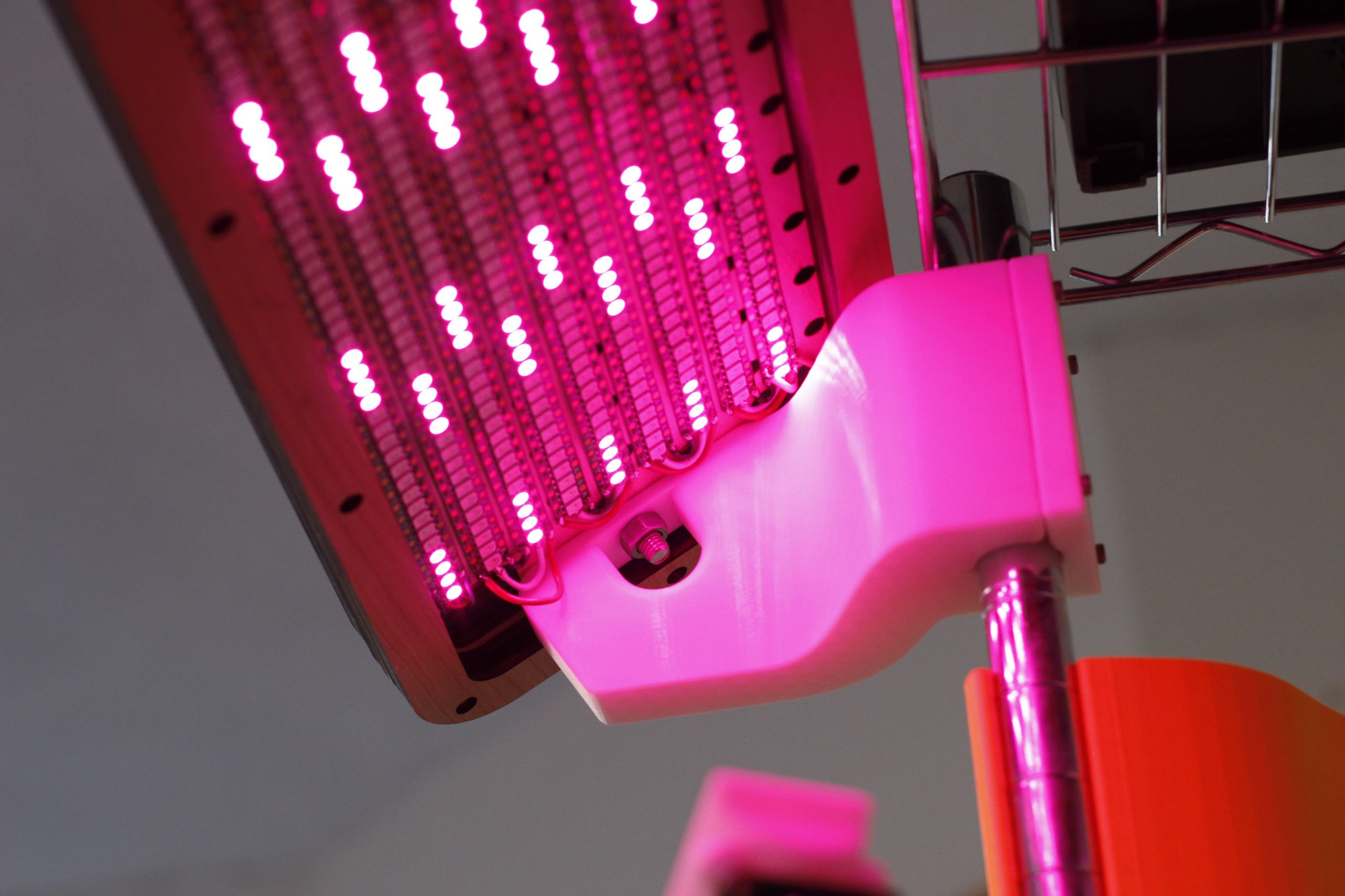
Luckily, one element of the installation that I was able to retain possession of after the installation concluded was the LED matrix. An overwhelming array of 1215 addressable LEDs, and a 100W power supply to drive them.
Still brimming with usefulness, and valuable as a totem commemorating the successful project, the light bar was filed into storage. Unfortunately, I lacked the bandwidth and inspiration to pick it back up. In the past few months however, on quiet nights, I could hear it calling out to me from the crawlspace, pleading to be reanimated. And after a few years of rest, this post describes how this favorite project is given a new lease on life to enhance my 3D printing workflow.
The first revision of this project was shipped in November of 2020, but the subsequent redesign was commissioned and completed the following summer in 2021. This post primarily a journey through that second revision, and it’s publication comes some time after the deliverable was shipped to the client.
Engineering requirements that arrive downstream from artistic intent are my favorite constraints to work inside of. It forces the engineer to assume the role of the artist, considering the feelings and ideas that will be communicated to the audience with the piece. The engineer also has to become an audience member to understand other factors about how viewing will take place, if the environment will change such that the piece needs to respond in kind. The space in between these to roles needs to be projected into the standard space of product requirements, weights, tolerances, latencies etc. that are common in the profession.
As a part of my freelance practice, interdisciplinary artist Sara Dittrich and I recently collaborated on a series of projects, adding to our shared body of work. The most technically challenging part of these most recent works was a component of her piece called The Tender Interval. I urge you to go read her documentation on this project, there is a great video overview as well.
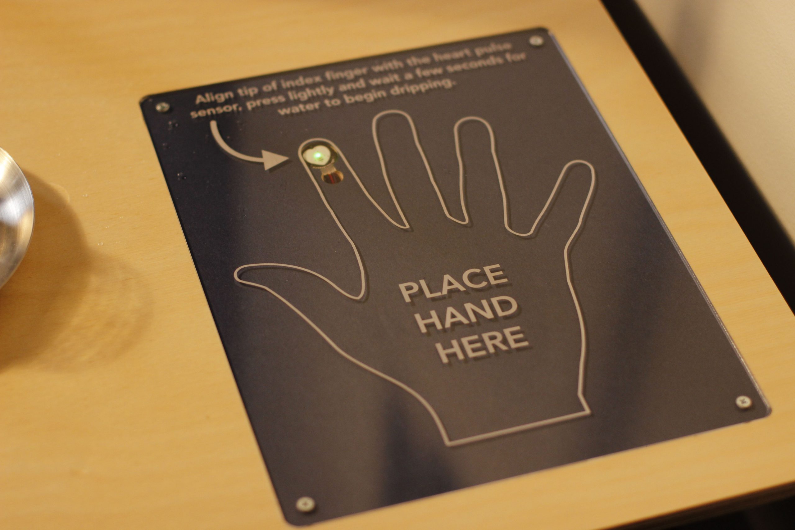
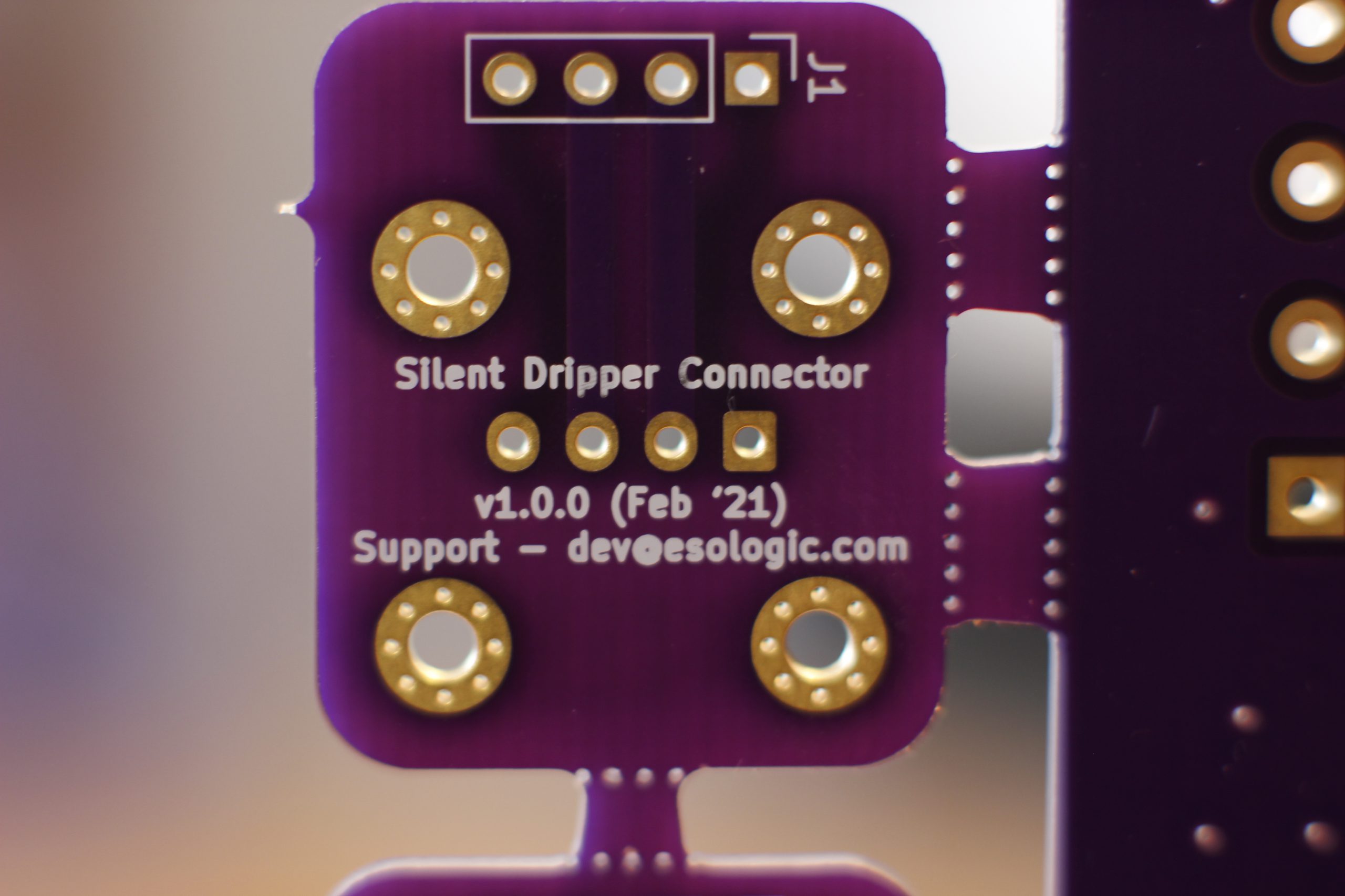
Two performers sit at a table across from each other, above them is an IV stand with two containers full of water. Embedded in the table are two fingerprint sensors, one for each of the people seated at the table. Performers place their hands on the table, with their index fingers covering the sensors. Each time their heart beats, their container emits a single drop of water, which falls from above them into a glass placed next to them on the table. Once their glass fills, they drink the water. Optionally, virtual viewers on twitch can take the place of the second performer by sending commands on twitch that deposit water droplets into the second glass.
Design and manufacture of table and this insert were completed by Sara Dittrich
The device responsible for creating the water droplets (the dripper) ended up being a very technically demanding object to create. The preeminent cause of this difficulty was the requirement that it operate in complete silence. Since the first showings of this piece were done virtually due to the pandemic, we were able to punt this problem and get the around noisy operating levels of V1 using strategic microphone placement. However, this piece would eventually be shown in a gallery setting, which would require totally silent operation.
The following is a feature overview and demonstration of the completed silent dripper:
If you’re interested in building one of these to add to your own projects, there is a github organization that contains the:
Per usual, please send along photos of rebuilds of this project. Submit PRs if you have improvements, or open issues if your run into problems along the way.
The rest of this post will be a deep dive into earlier iterations of this project, and an closer look at the design details and challenges of the final design. It’s easier to understand why a second iteration was needed after reviewing the shortcomings of version 1, so that’s where we’ll start.
Edit: This project was completed hackathon-style in a matter of days. I’ve been working to optimize the design and sell kits, follow along here.
Here’s a (long winded) video overview of this project:
Background
Rendered desperate for VRAM by a forthcomingnow released! stylegan-related project, I recently had to wade thermistor first into the concernedly hot and strange world of GPUs without video outputs to design a high performance cooler for the NVIDIA Tesla K80.
Too esoteric to game on, and too power hungry to mine cryptocurrencies with, the K80 (allegedly the ‘The World’s Most Popular GPU’) can be had for under $250 USD on ebay, a far cry from it’s imperial MSRP of $5000. By my math, the card is one of the most cost-efficient ways to avail one’s self of video ram by the dozen of gigabytes.
This sounds great on paper, but actually getting one of these configured to do useful work is a kind of a project in, and of itself. I’ll eventually get to this in the aforementioned upcoming post. Today’s topic however, is upstream of all that: the task of keeping these things cool.
Check out this comment for some tweaks to this guide to support the latest version of the tools!
Panelization is the process of taking two or more PCB designs and combining them using tabs or v-scores that you would then separate into individual boards once they come back from manufacturing. It’s a way to get more than one design made in a single order.
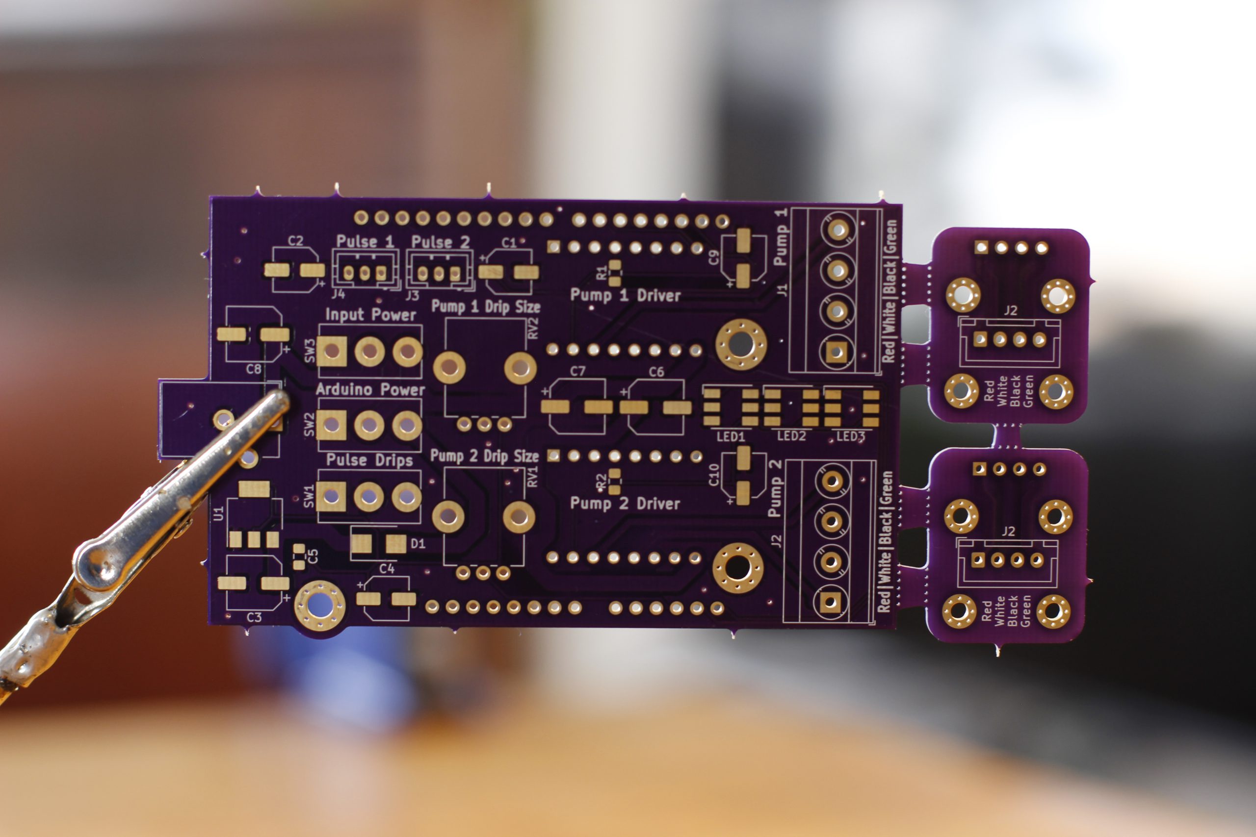
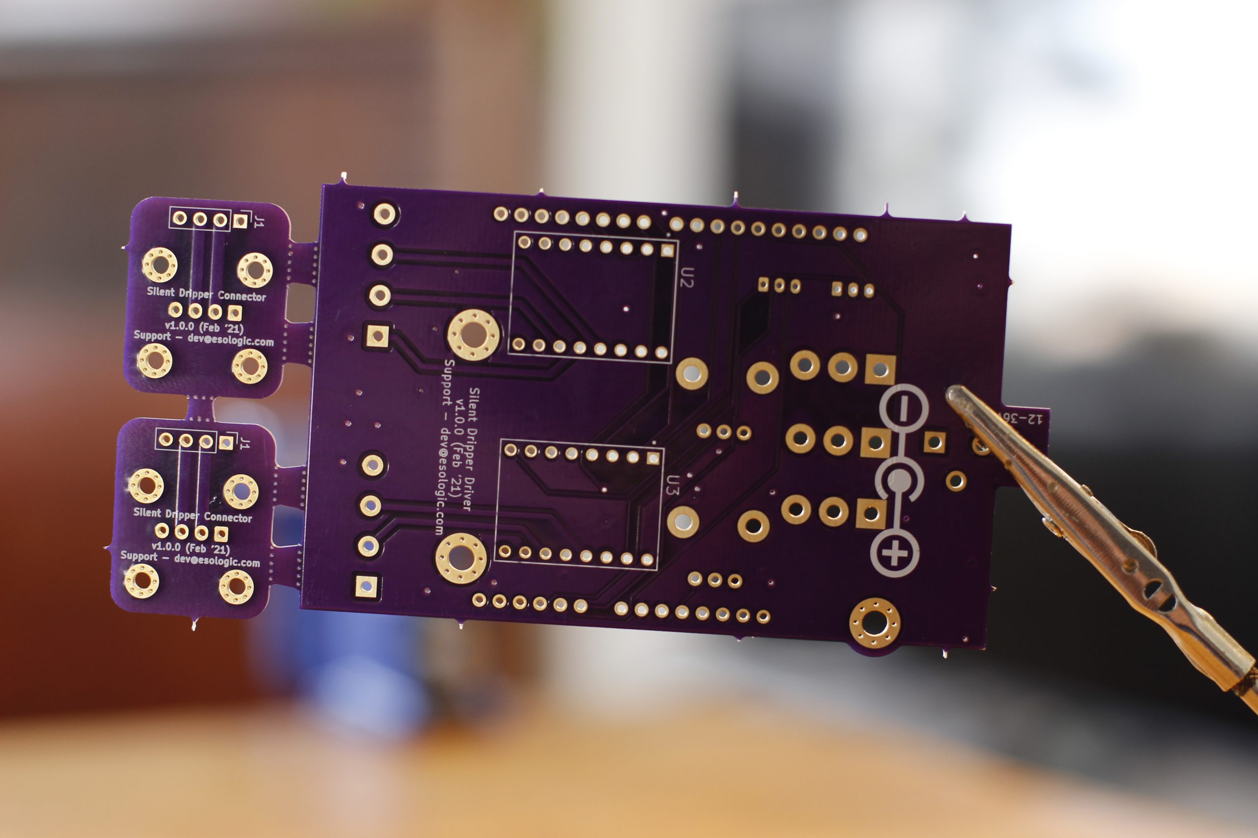
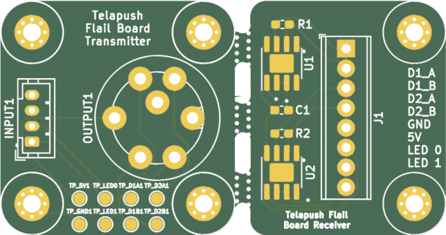
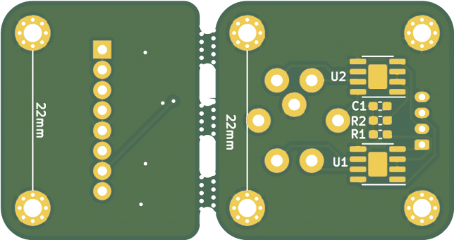
There are a few forum posts or other snippets on how to accomplish this out there already, but not a real guide. For my own sake, this is how you can do this panelization using all free tools. Here are some photos of a board I had fabricated by OSH Park using this panelization method:
I implement this technique whenever I’m creating closely-related PCBs.
The design highlighted in this blog post is a transmitter/receiver pair, meaning that there would never be a transmitter without a receiver, or vice-versa.
Design is made simple by doing the layouts individually, and manufacturing is made simple by getting them made as a single board, not having to coordinate multiple orders. Let’s get started with the guide.
1. Download The Tools
You probably already have KiCAD. Next, make sure to download GerberPanelizer by This is not Rocket Science (site link) from GitHub. This guide uses the 2018-08-10 snapshot release.
2. Export your designs from KiCAD
Your designs have to be completely ready for production before starting this process. Components placed, tracks laid, zones poured etc. It is very “one-way” in that it is impossible to update an already panelized design once it has been exported.
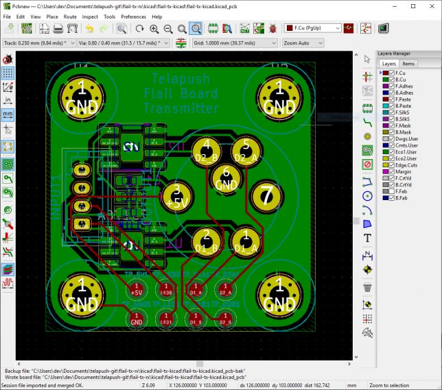
Here’s one of the designs that will be added to the panel.
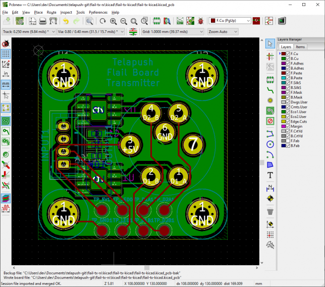
You’ll want to add a grid origin that is really close to your design. In KiCAD, select place → grid origin to do this. I am putting it in the top left hand corner of the board.
Grid origin placed
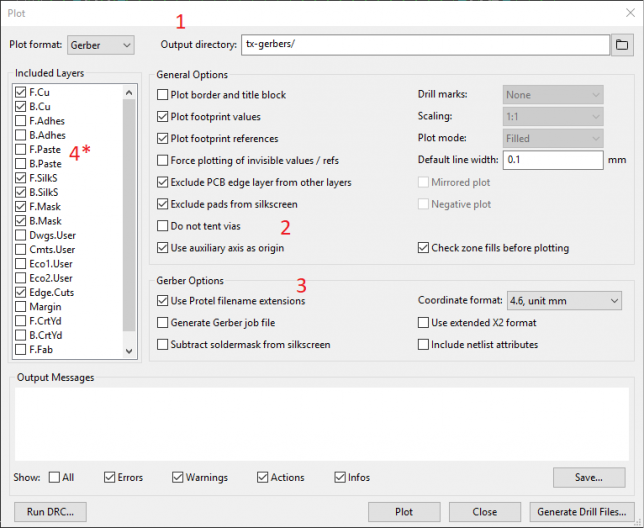
In pcbnew, select file → plot to adjust the gerber export settings.
Make sure Output directory is set to an empty directory somewhere on your disk. In this example, it’s set to tx-gerbers.
Check Use auxiliary axis as origin
Check Use Protel filename extensions
*Optional* Since I’m not using them in this design, I’ve unchecked F.Paste and B.Paste.
And then click Plot.
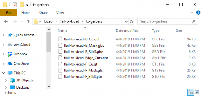
You should be greeted with a directory of files with dissimilar extensions:
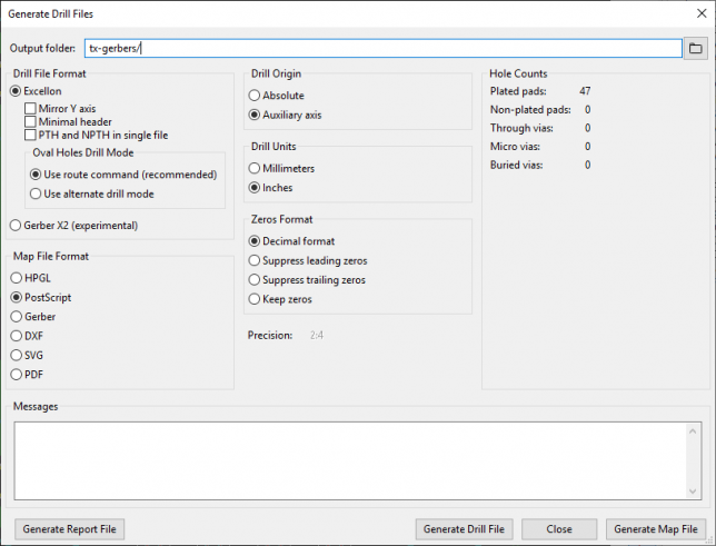
These settings will automatically be set to match the previous export, but make sure the output folder and the drill origin match the previous settings. Mine looked like this:
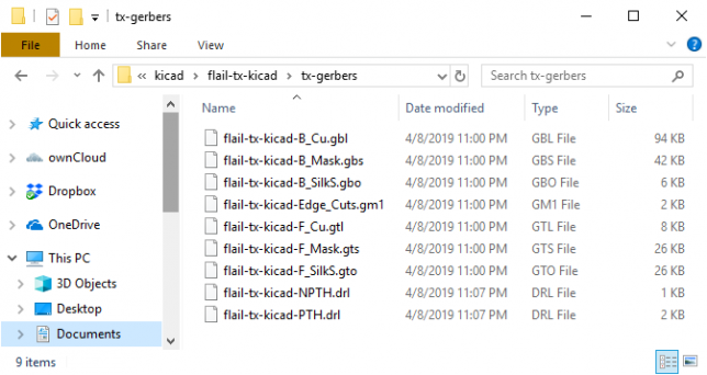
Here is my resulting output directory with all of the files:
3. Modify the exported files
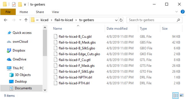
This step is weird. You need to change the extension of all .gm1 files to .gko. For this example, flail-tx-kicad-Edge_Cuts.gm1 needs to be renamed to flail-tx-kicad-Edge_Cuts.gko as this is what GerberPanelizer expects. Here is my resulting directory:
Notice the .gko file
4. Load the designs into Gerber Panelizer
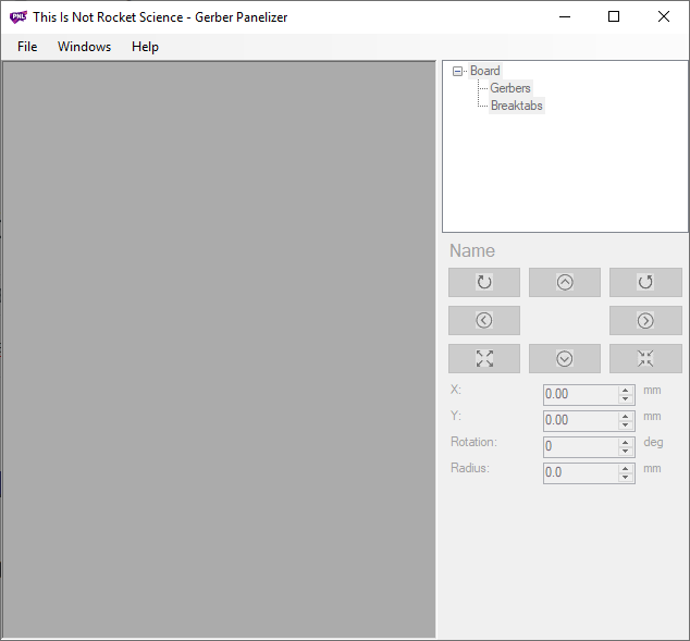
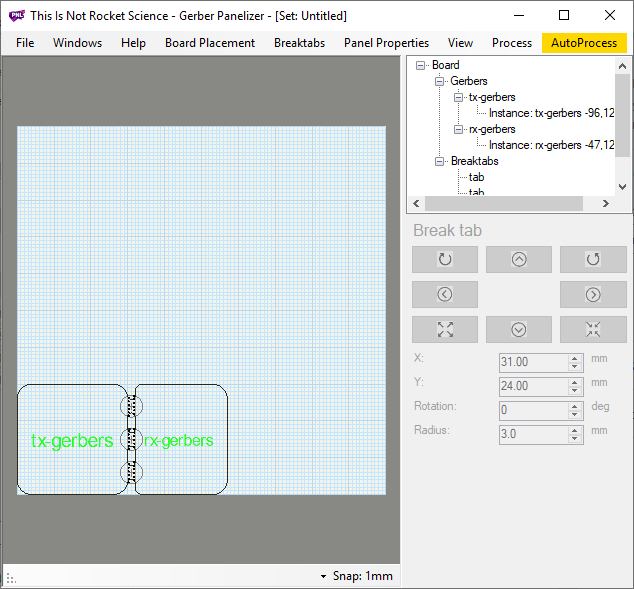
Open up GerberPanelizer, you will be greeted with this screen:
Select file → new to create a new project. Next, select board placement → add gerber folder and navigate to the output folder from KiCAD. In this example, it was tx-gerbers.
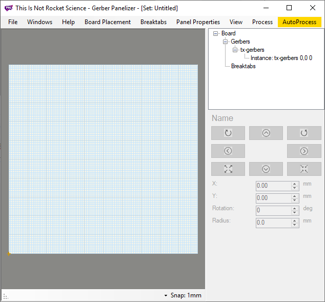
You should be seeing something like this:
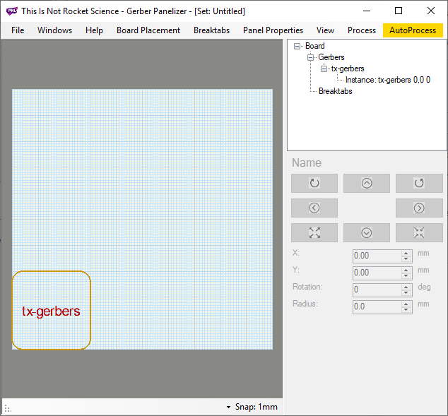
Where is the board?! Select board placement → autopack: native and your design will leap into view:
Now, re-do the guide up until this point for however many unique designs you want to add to this panel. If you want to duplicate your design multiple times in the same panel, you can add an instance by right clicking on the instance in the right hand view and then clicking add instance.
5. Arrange designs and add tabs
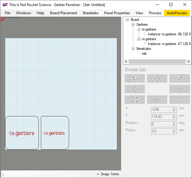
Since you’ve been hitting board placement → autopack: native after each board add, your designs should be properly arranged at this point. You can manually move the designs by clicking and dragging them, but I’ve found that using the autopack works really really well. Here’s what my design looks like at this point:
To join the designs together, you need to add breaktabs.
Select breaktabs → insert breaktab, and a small red circle will appear in the top left hand corner of the workspace:
Click and drag the tab between the two designs. Make sure black dots appear on either edge of the design:
Continue to add tabs in the same manner until the text turns a bright green color, this lets you know that the boards will be secured.
There is no way to automatically add the proper tabs, so make sure you use your best judgement.
Now we’re ready to export!
6. Export the panelized design
It’s a good idea to first save the design in GerberPanelizer so you can edit the layout later without having to start from scratch. Once you export the final merged gerber files, they cannot be edited or re-arranged. Select file →save as to save the project.
Now to export the gerbers.
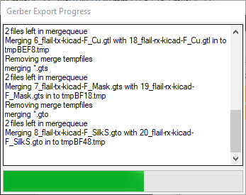
Again, in GerberPanelizer, select file → export merged gerbers and choose an empty output directory. The directory has to be empty because you typically send a zip archive of all gerbers to the manufacturer to get made, and this zip archive should just include this export. You should see this window pop up:
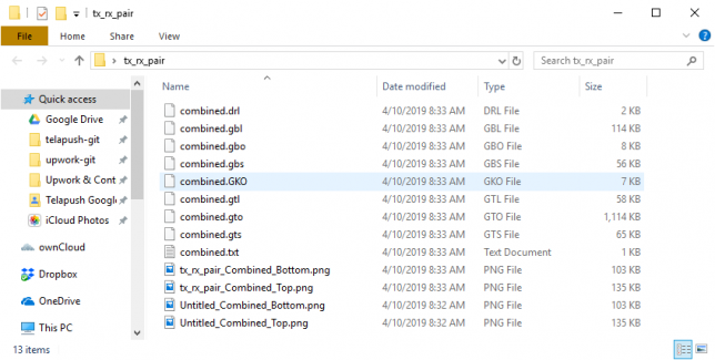
The contents of the merged output directory should look like this:
The merged output directory will include several image renderings of your merged designs, this is a great first check to make sure that everything went well.
Looks good! However before you send any critical designs off for manufacturing it’s best practice to visually inspect the layers with a gerber viewer. Save the merged output directory as a .zip file.
7. Verify using GerbView
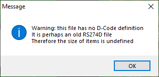
KiCAD ships with a program called GerbView to inspect gerber files. Open that gerbview and then open your zipped merged output directory with file → open zip archive file.
There will be an error message which you can ignore.
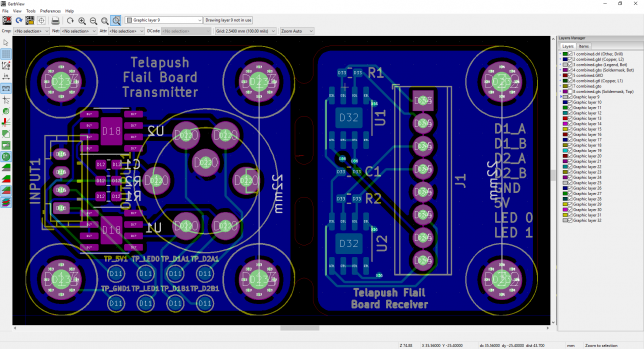
You should see something like this:
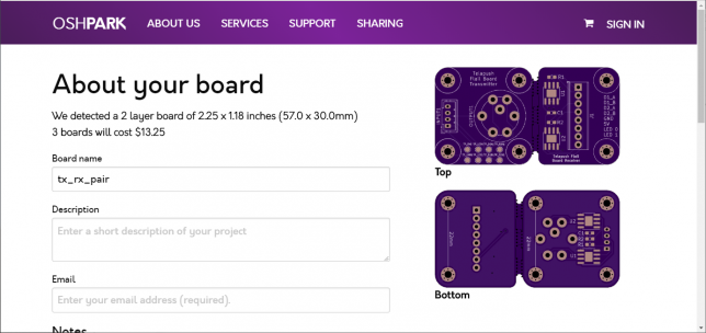
There’s the design as we expect it, you can uncheck the different layers on the right pane just like in pcbnew to inspect them one by one. I’ve uploaded this design to oshpark (a domestic PCB fab service) to see if their preview also looks correct and again, there are no problems.
You’re now ready to send your panelized designs out for manufacturing. Congrats!
8. Wrap up
Thanks for reading! Did this guide work for you? Let me know in the comments below this post.
Note: This is confirmed to work with KiCAD 4 and 5.
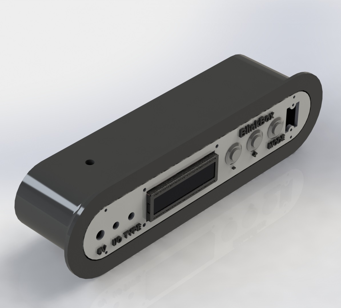
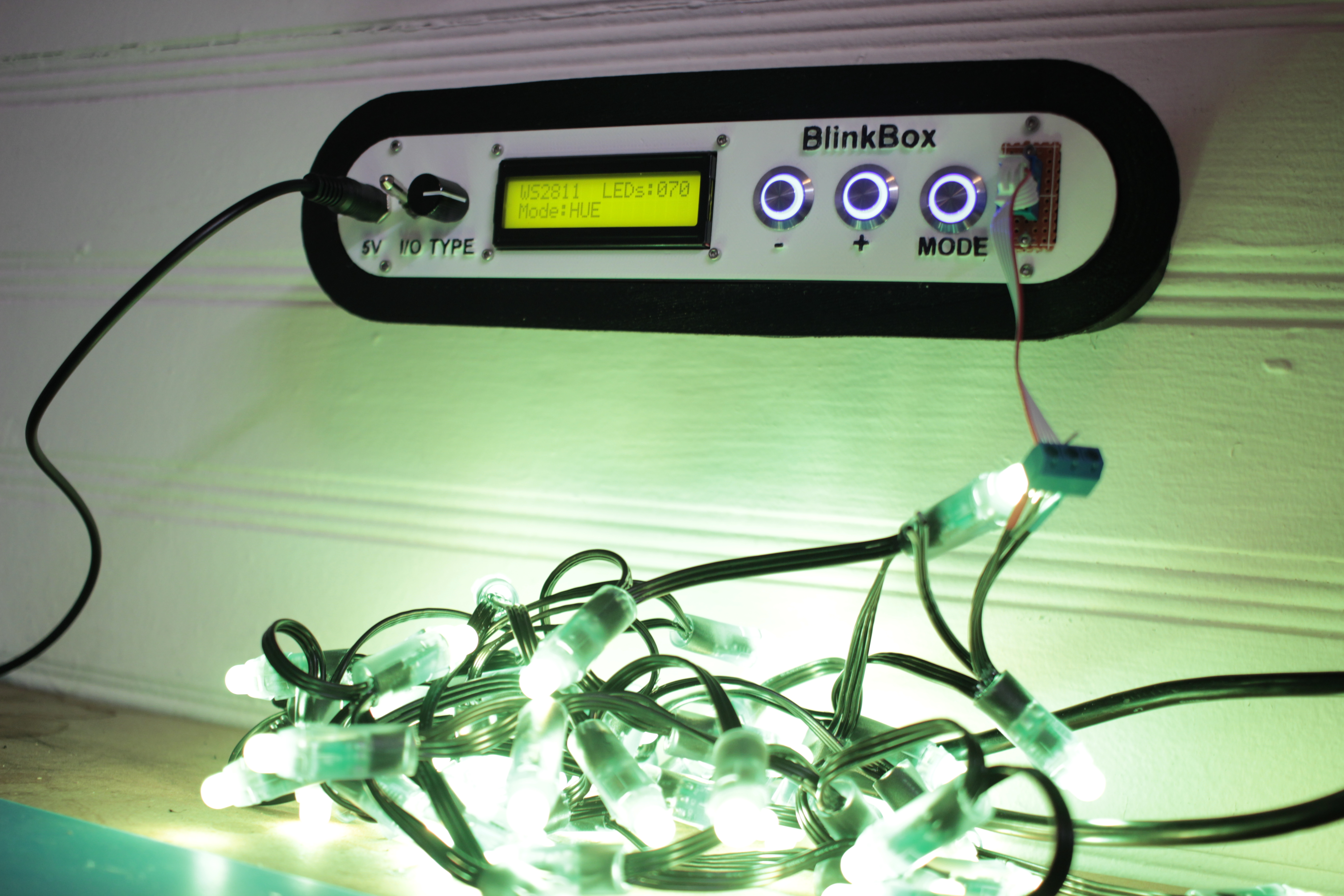
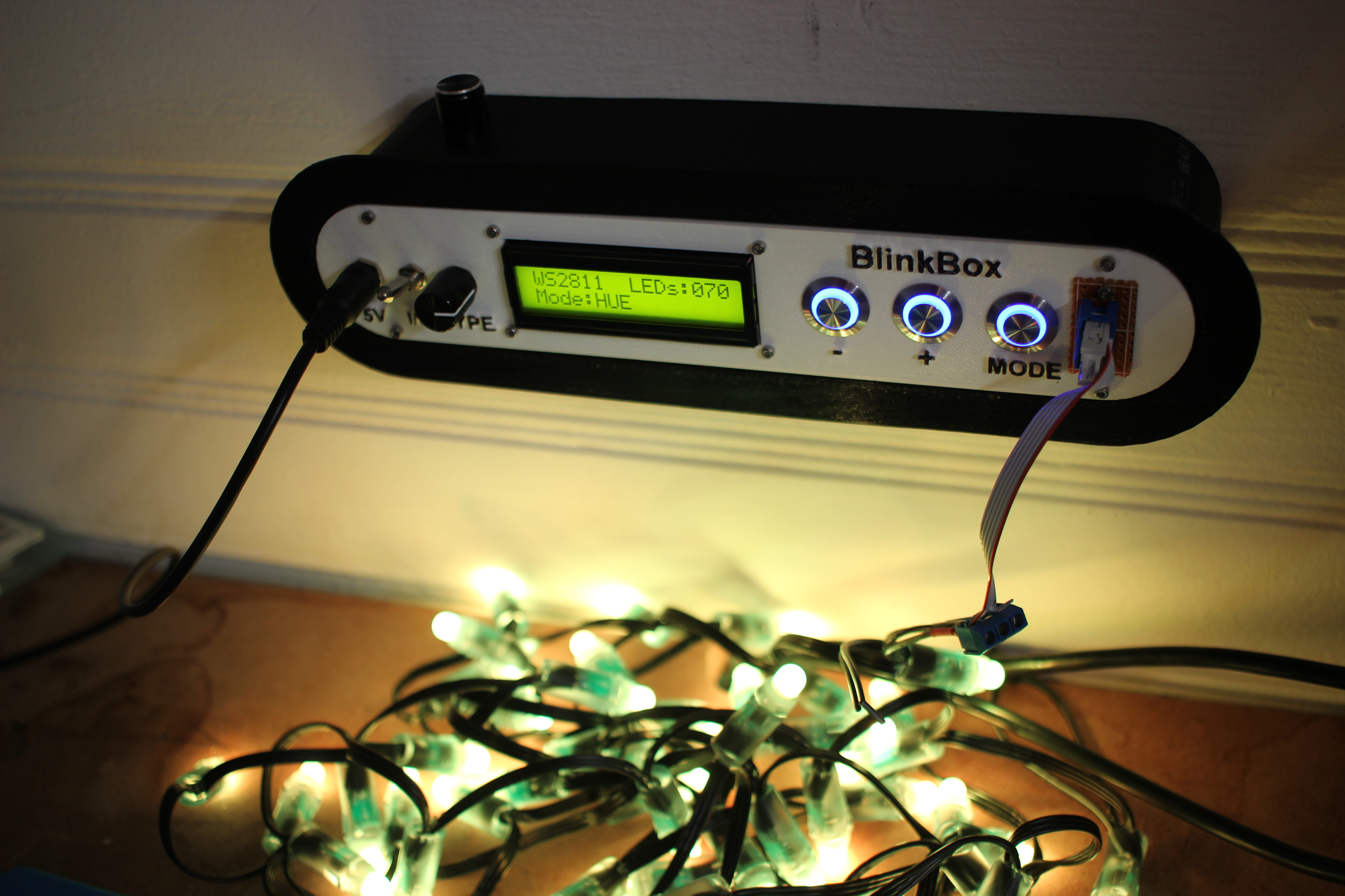
I work with addressable LEDs a lot. For all that they’re great for, they’re kind of hard to debug when you have a lot of them connected up at once. This is especially apparent when you have many small single modules in hard to reach spaces.
Here’s my solution:
This lets me set the color and number of LEDs in a strip, and then displays a color pattern. This way I can tell if an LED has become disconnected in a strip, or if a channel inside a particular has died.
Features
Select LED type with the type switch, 4 positions
Can test up to 400 LEDs at a time, if you can find a worthy power supply
3 Test modes
RGB – 1 second red, 1 second green, 1 second blue
HUE – Lock strip at HSV (x, 255, 255) and x loops from 0-255
WHTE – Set the strip to RGB(255, 255, 255)
Count and Mode are saved into eeprom, so you don’t have to keep resetting the strip if it powers off
Wall mount fittings
Design Explanation
All of the raw code solidworks, and KiCAD have been posted on my github. You can look at the 3D models on thingiverse as well.
Mechanical
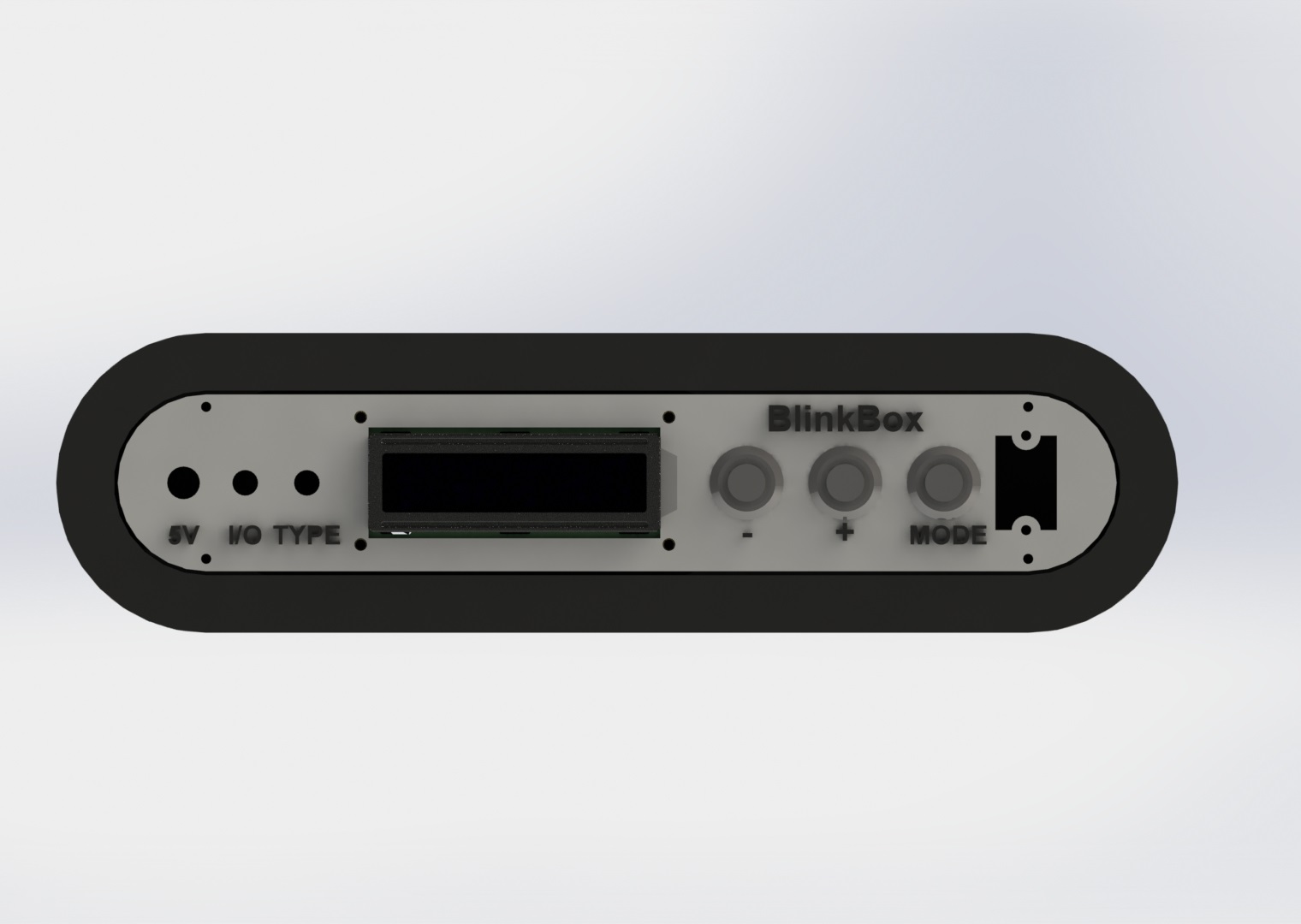
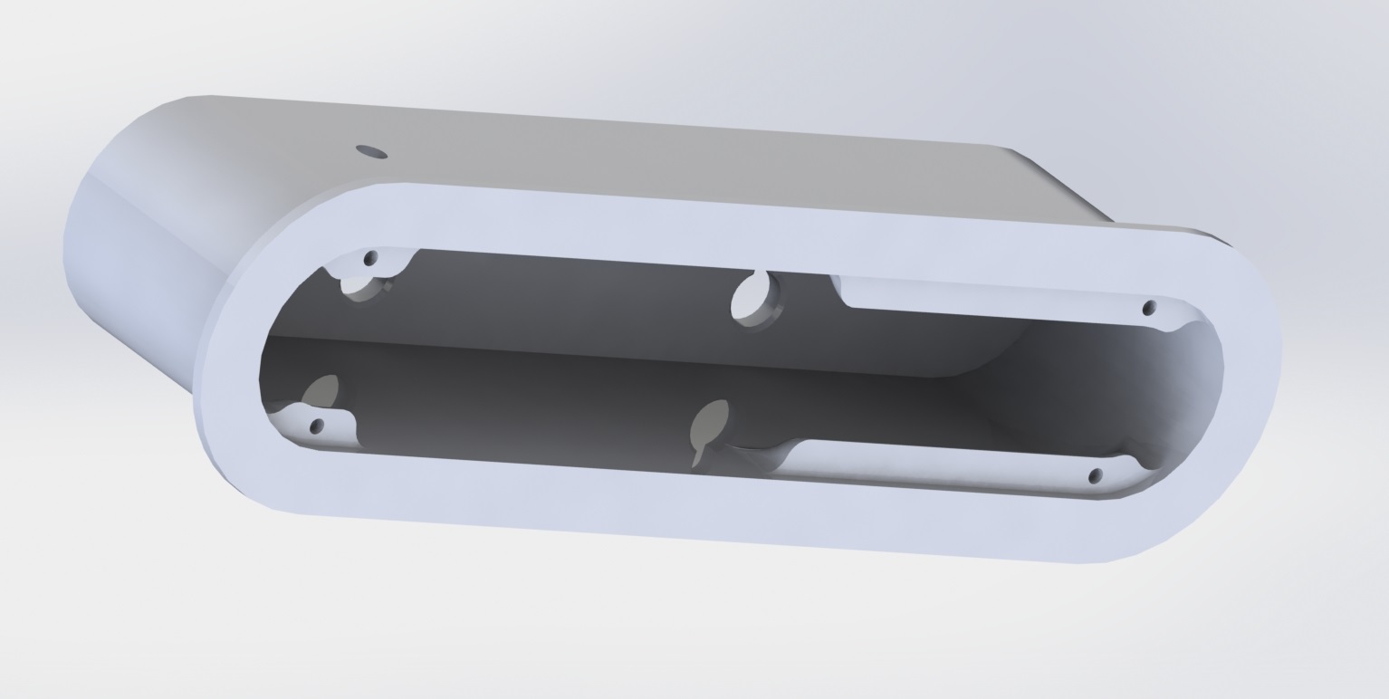
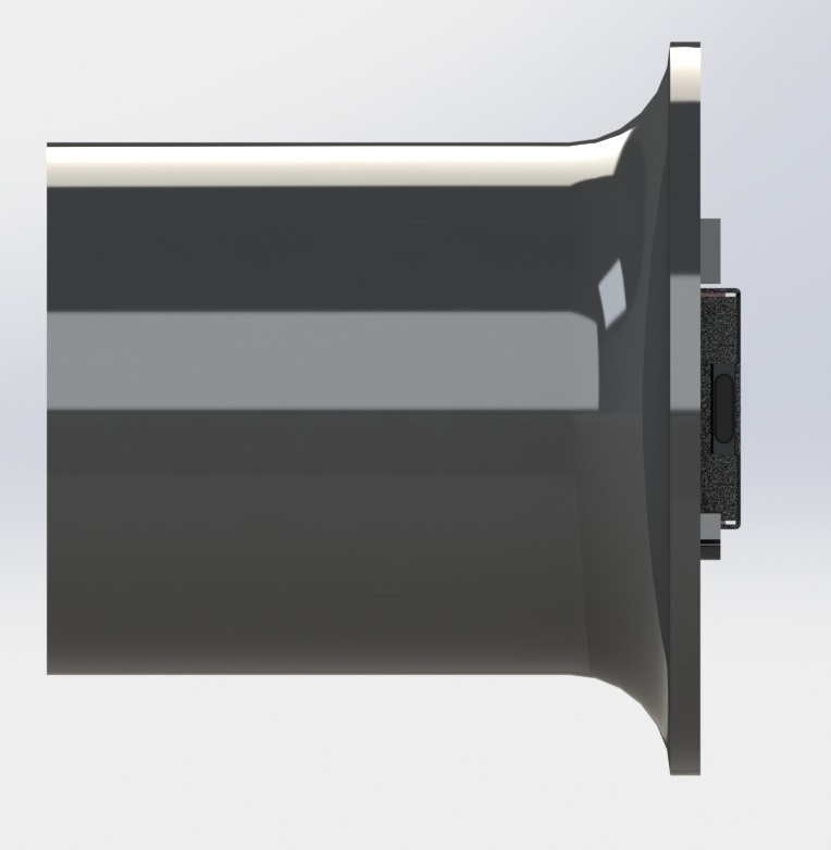
Here are a couple of quick renders of the assembly design:
The screw mount behind the pushbuttons is extended to be able to support the pressure without flexing: I added a ridge so you can grab onto something as you interact with the switches / buttons.
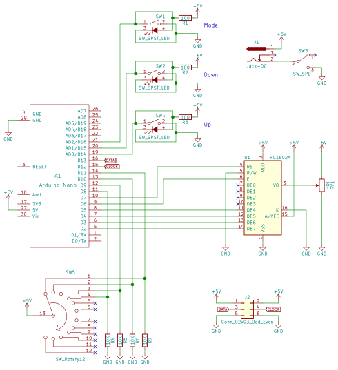
Electronics
Here’s the circuit:
There really isn’t a lot going on here, the parts are probably the coolest part of the project. The 5V jack is a 6mm DC barrel jack, the pushbuttons are illuminated 16mm pushbuttons from adafruit, the on/off switch is a locking toggle switch, and the 4 position rotary switch can be found here.
I wired up the circuit on a spare piece of perfboard.
The LED driving part of the code is based on FastLED, a beautiful library for driving these types of addressable LEDs.
The rest of the code is mostly just a hardware UI problem, and isn’t all that interesting. LED count “ramps” as you hold the button down. The longer you hold the button, the faster the
Wrap up
That’s pretty much it! I’ve already gotten some use out of this tool and have found great satisfaction in taking the time to make it look nice as it will be a permanent addition to my lab.
I’ll post any updates I make to this project as edits to the top of this post.
Thanks for reading, and here are a few more photos:
Ever wanted to measure the frequency of a square wave using an Arduino? There are a couple of good solutions out of there to do this, but not all of them had the capacity to do multiple inputs. I couldn’t find this quickly so here is my solution.
Here’s the link to the code if you want to skip ahead. The code uses interrupts and doesn’t use any kind of delaying so it’s good for giant state-machine applications. My application for this is measuring signals from 10Hz-100Hz in which this can measure within 1% error. The absolute limits of the code are 1Hz-50KHz.
This project is on GitHub if you want to send a pull request to make improvements.
Setup
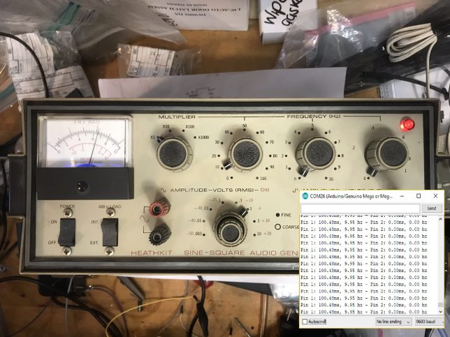
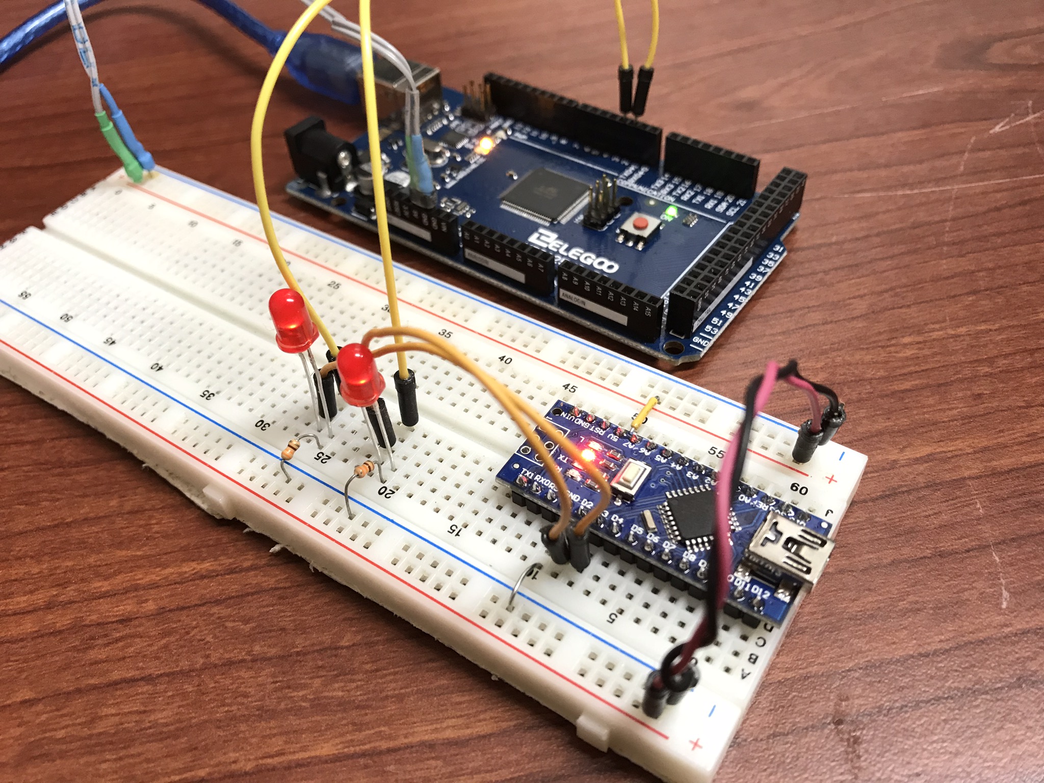
For testing, I wrote a simple function generator and uploaded it to a separate arduino. It outputs a pulse train with periods of 10ms (100Hz) and 5ms (200Hz) on pins 2 and 3. I attached LEDs and their resistors for debugging.
Pins 2 and 3 on the function generator to pins 2 and 3 on the frequency counter.
The code for this simple function generator is here:
This code will work fine in a stateless application, because there are no delay statements (which some other frequency counters I’ve seen online use). It’s a little bit complicated, send me a pull request if you can refactor it to be cleaner.
Here’s the sketch:
/*
 * 3/29/2018 - Devon Bray - https://www.esologic.commultiple-frequency-counter-arduino/
 *
 * I've written most of the important notes as comments in the source, but a couple more details:
 *
 * - The important data is stored in `period_averages_ms` and `frequency_averages_hz`. You address them using the indices defined at the top of the file. These arrays get updated each time `compute_counts()` is called. Keep it `compute_counts()` somewhere in the main() loop.
 *
 * - You could easily add more frequencies, you just have to `NUMSIGS`, make a specific ISR, and another `attachInterrupt` line in setup()
 *
 * - It uses [interrupts](https://playground.arduino.cc/Code/Interrupts) which might not be right for your proejct, but normally shouldn't get in the way of too much stuff.
 *
 * - If the ISR hasn't seen a new edge in 1000000us, both `period_averages_ms[p_index]` and `frequency_averages_hz[p_index]` will be set to zero!
 * - This means that slowest frequency that this code can detect is 1hz!
 *
 */

int freq_pin_1 = 2; // the pin connected to the first signal, must be an interrupt pin! See the arduino docs
int freq_pin_2 = 3; // the pin connected to the second signal, must be an interrupt pin! See the arduino docs

#define BUFFSIZE 100 // a rolling average of the frequency/period is computed, and this is the size of that buffer

#define NUMSIGS 2
#define FREQ1INDEX 0
#define FREQ2INDEX 1

volatile int period_buffer_indices[NUMSIGS] = { 0 }; // the location of the index for adding to the rolling buffer average
volatile unsigned long period_buffers[NUMSIGS][BUFFSIZE] = { 0 }; // the buffers
volatile unsigned long previous_edge_times_us[NUMSIGS] = { 0 }; // the time that the previous edge came in in microseconds
volatile float period_averages_ms[NUMSIGS] = { 0 }; // the period time of a given signal in milliseconds
volatile float frequency_averages_hz[NUMSIGS] = { 0 }; // the frequency of a given signal in hertz
volatile bool period_buffer_locked[NUMSIGS] = { false }; // spin locks for the different buffers

void setup() {

  Serial.begin(9600);

  // the pins must be mapped to their ISRs

  pinMode(freq_pin_1, INPUT_PULLUP);
  attachInterrupt(digitalPinToInterrupt(freq_pin_1), new_freq1_edge, RISING); // you could change this mode to whatever you were looking for, FALLING, CHANGE etc.

  pinMode(freq_pin_2, INPUT_PULLUP);
  attachInterrupt(digitalPinToInterrupt(freq_pin_2), new_freq2_edge, RISING);
}

void loop() {

  compute_counts();

  Serial.print("Pin 1: ");
  Serial.print(period_averages_ms[FREQ1INDEX]);
  Serial.print("ms, ");
  Serial.print(frequency_averages_hz[FREQ1INDEX]);
  Serial.print(" hz");

  Serial.print(" - Pin 2: ");
  Serial.print(period_averages_ms[FREQ2INDEX]);
  Serial.print("ms, ");
  Serial.print(frequency_averages_hz[FREQ2INDEX]);
  Serial.print(" hz");
  Serial.println("");
}

void compute_counts() {

  // computes the average of the buffer for a given signal. Must be called before using the period_averages_ms or frequency_averages_hz buffers.

  for (int p_index = 0; p_index < NUMSIGS; p_index++) {

    float buffer_sum = 0;

    while (period_buffer_locked[p_index]) {}; // wait around for the ISR to finish

    period_buffer_locked[p_index] = true; // ISR won't add new data to `period_buffers`
    if ((micros() - previous_edge_times_us[p_index]) < 1000000) {
      for (int j = 0; j < BUFFSIZE; j++) {
        buffer_sum += period_buffers[p_index][j];
      }
    }
    period_buffer_locked[p_index] = false; // ISR will now add new data to `period_buffers`

    if (buffer_sum > 0){
      period_averages_ms[p_index] = ((buffer_sum / (float)BUFFSIZE)) / 1000;
      frequency_averages_hz[p_index] = (1 / period_averages_ms[p_index]) * 1000;
    }
    else {
      period_averages_ms[p_index] = 0;
      frequency_averages_hz[p_index] = 0;
    }

  }
}

void new_edge(int period_index) {

  unsigned long current = micros();

  if (period_buffer_locked[period_index] == false) { // if compute_counts is using the buffer, skip adding to it because that process isn't atomic

    period_buffer_locked[period_index] = true;

    period_buffers[period_index][period_buffer_indices[period_index]] = current - previous_edge_times_us[period_index];

    period_buffer_locked[period_index] = false;

    period_buffer_indices[period_index]++;
    if (period_buffer_indices[period_index] >= BUFFSIZE) {
      period_buffer_indices[period_index] = 0;
    }
  }

  previous_edge_times_us[period_index] = current; // but make sure the new time is set because this operation is atomic

}

void new_freq1_edge() {
  new_edge(FREQ1INDEX);
}

void new_freq2_edge() {
  new_edge(FREQ2INDEX);
}
I’ve written most of the important notes as comments in the source, but a couple more details:
The important data is stored in `period_averages_ms` and `frequency_averages_hz`. You address them using the indices defined at the top of the file. Make sure you call `compute_counts()` before using this data. Keep it somewhere in main().
You could easily add more frequencies, you just have to `NUMSIGS`, make a specific ISR, and another `attachInterrupt` line in setup()
It uses interrupts which might not be right for your proejct, but normally shouldn’t get in the way of too much stuff.
If the ISR hasn’t seen a new edge in 1000000us, both period_averages_ms[p_index] and frequency_averages_hz[p_index] will be set to zero! This means that slowest frequency that this code can detect is 1Hz!
If you have any questions on how to add more signals, leave a comment!
Results
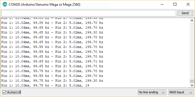
Here’s the output in the serial monitor attached to my function generator from earlier:
That’s like less than 1% error! Pretty good!
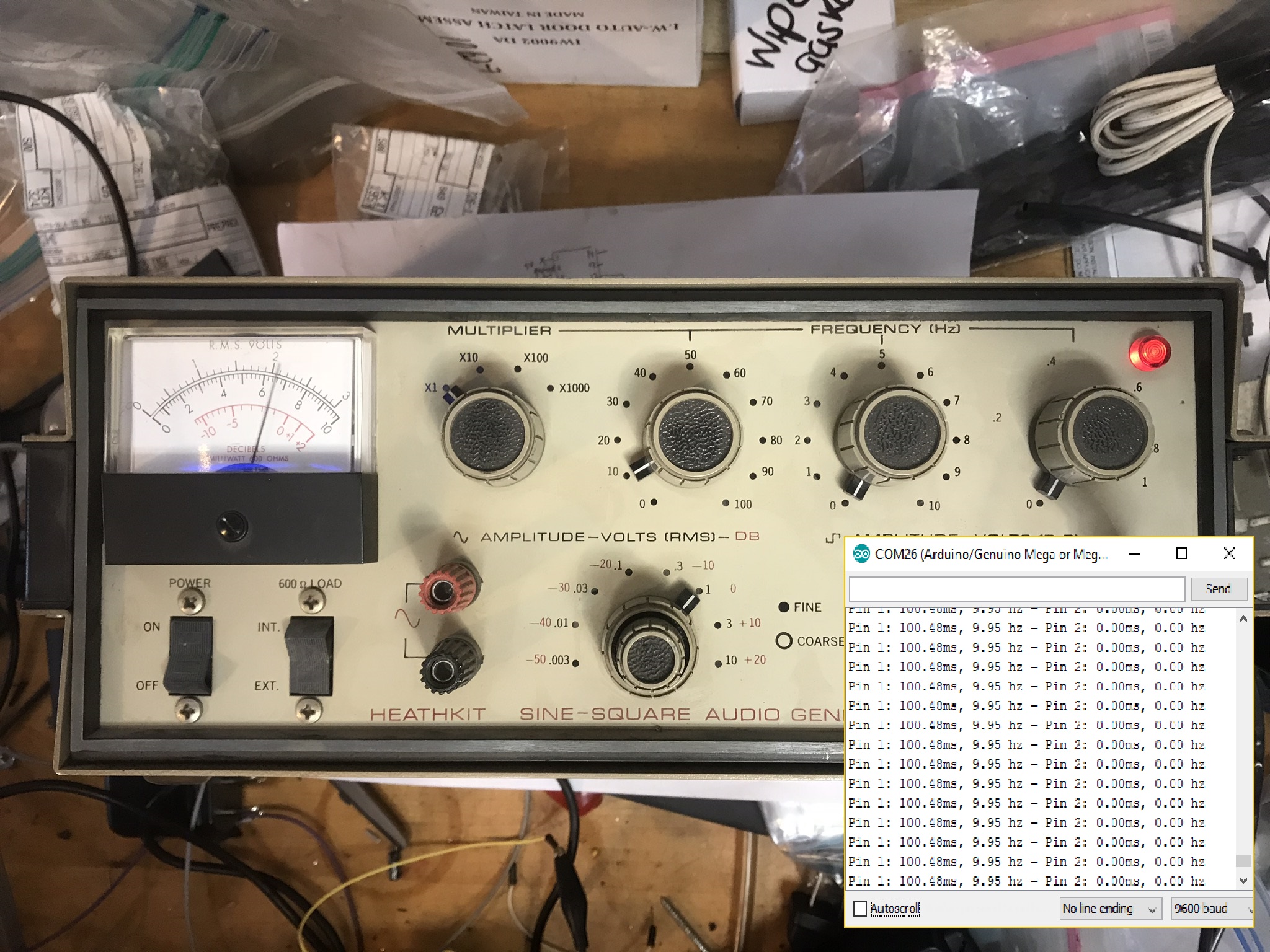
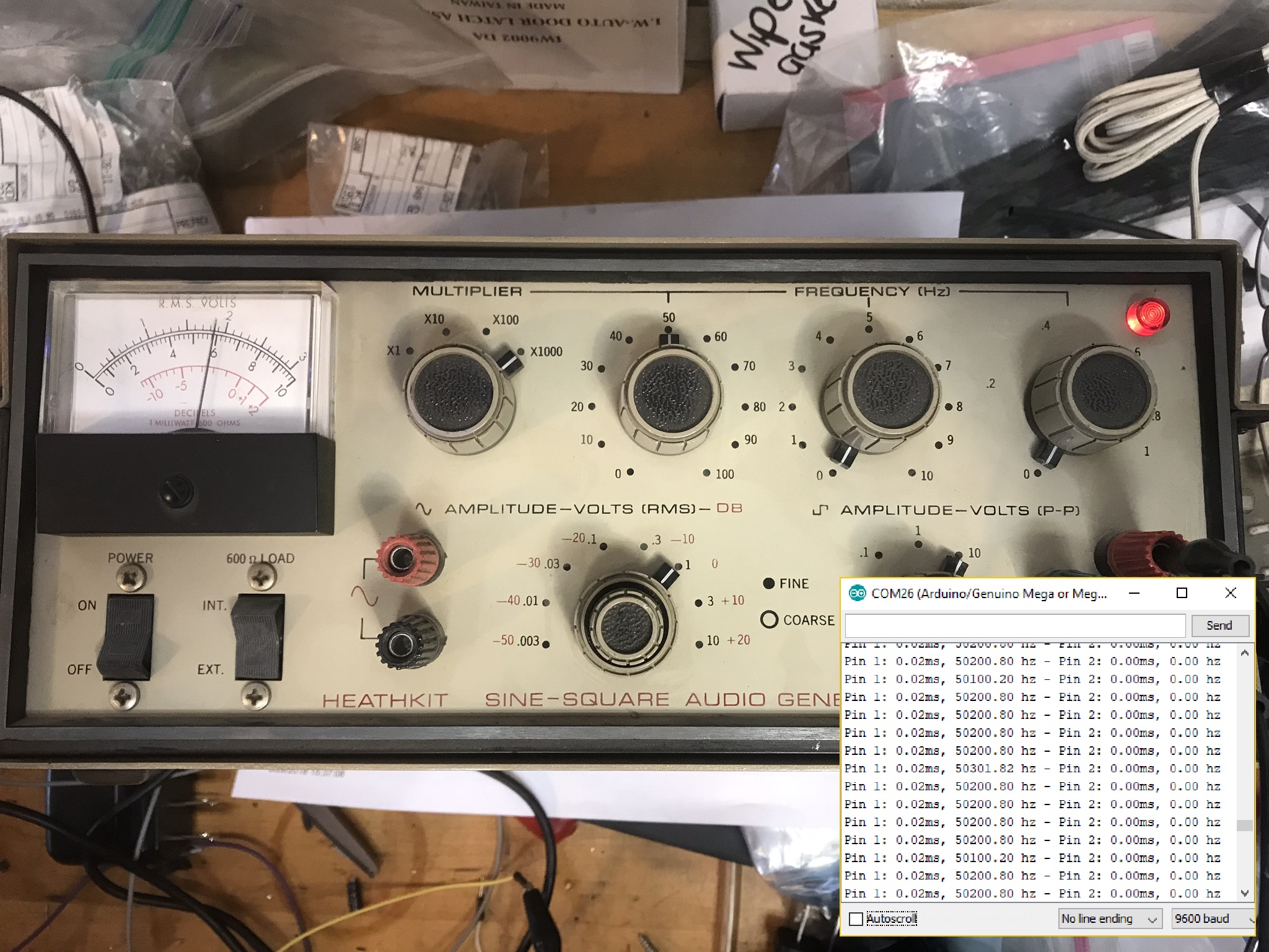
I also tested the code with a real function generator. Things worked really well until around 50KHz, so I would say that this code can’t be trusted past 50KHz.
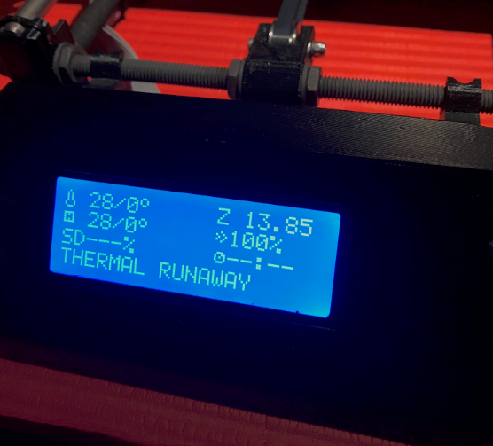
This time we’re trying to work through a hardware bug!
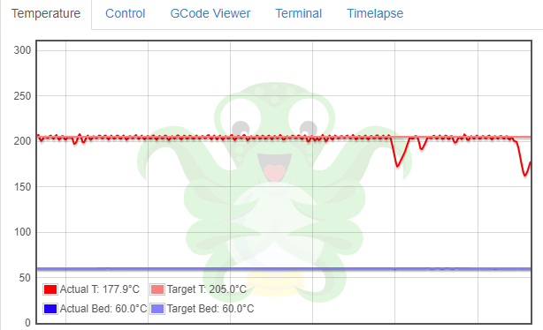
Without warning, my printer would stop it’s current print and display “THERMAL RUNAWAY” on the display screen:
This would happen once every couple of prints or so.
According Prusa’s Docs a common cause of this is problems with the thermistorconnection. They show a graph that has very erratic readings from the sensor:
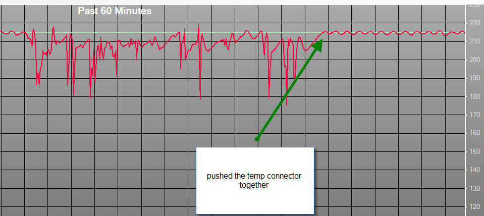
This seemed like a good place to start so I re-seated the connector and used octoprint to generate my own graph:
No erratic readings, the temp would drop off and then start heating back up.
The problem ended up being the connection between the terminal lug and the wire on the heater in the hotend. To fix this, I cut off the crimp lug and stripped away some insulation. I put this into the screw terminal block. I’ve done a couple of prints and had no issues after making this modification.
For my senior thesis project at WPI, myself and two colleagues (Rachael Putnam – RBE/ME and Mead Landis – RBE/ME) designed a tree climbing robot. I was in charge of designing and implementing the electronics and controls software. I was the most intense project I have ever worked on, both in terms of difficulty and potential impact. Here is our poster for project presentation day:
Here’s a video of the prototype climbing:
We did a blog during the project, here is the best post I wrote:


 This seemed like a good place to start so I re-seated the connector and used