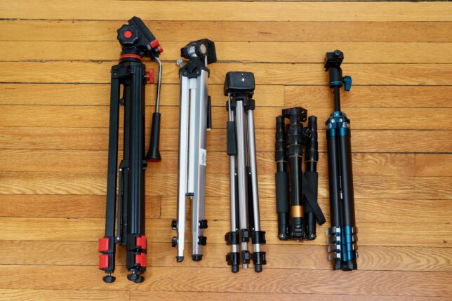
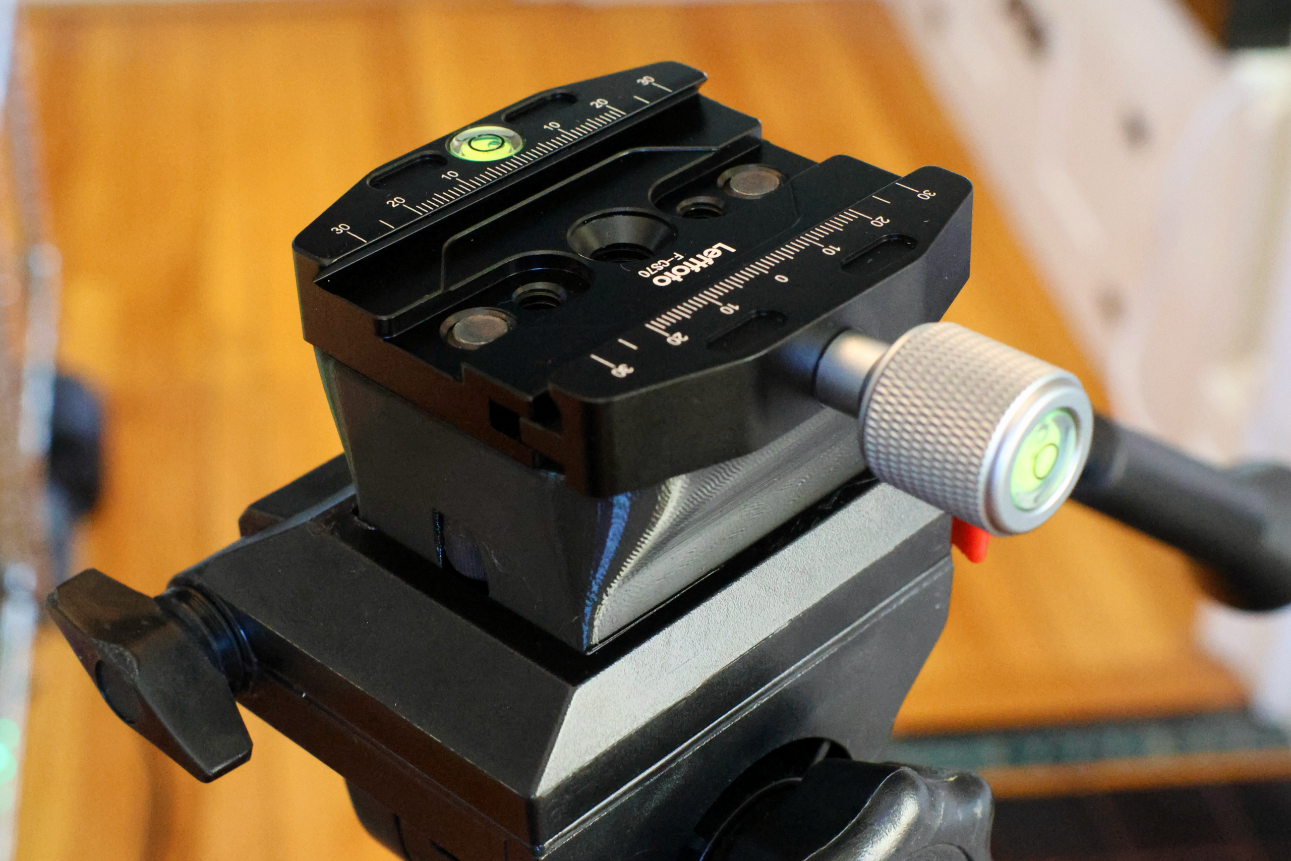
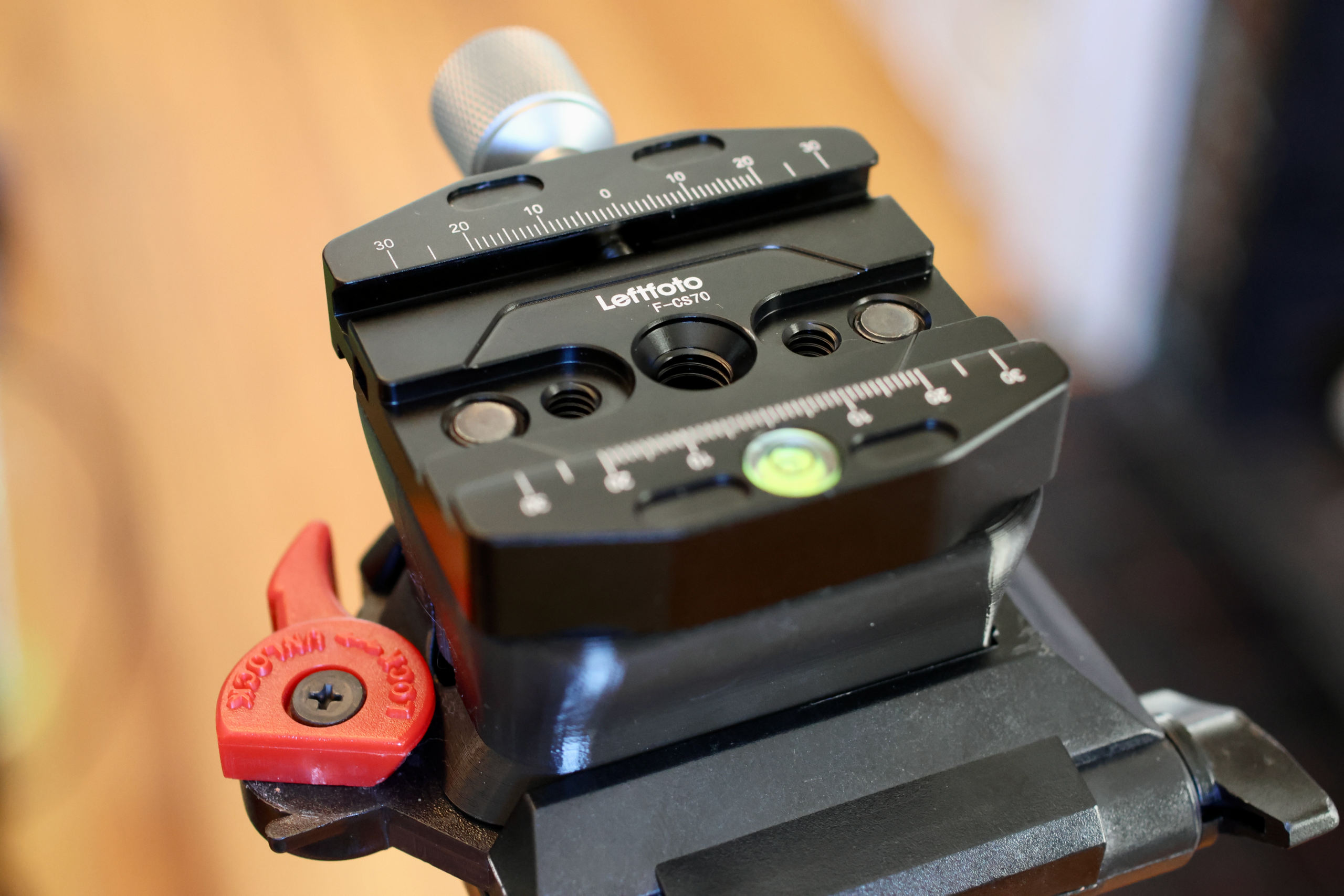
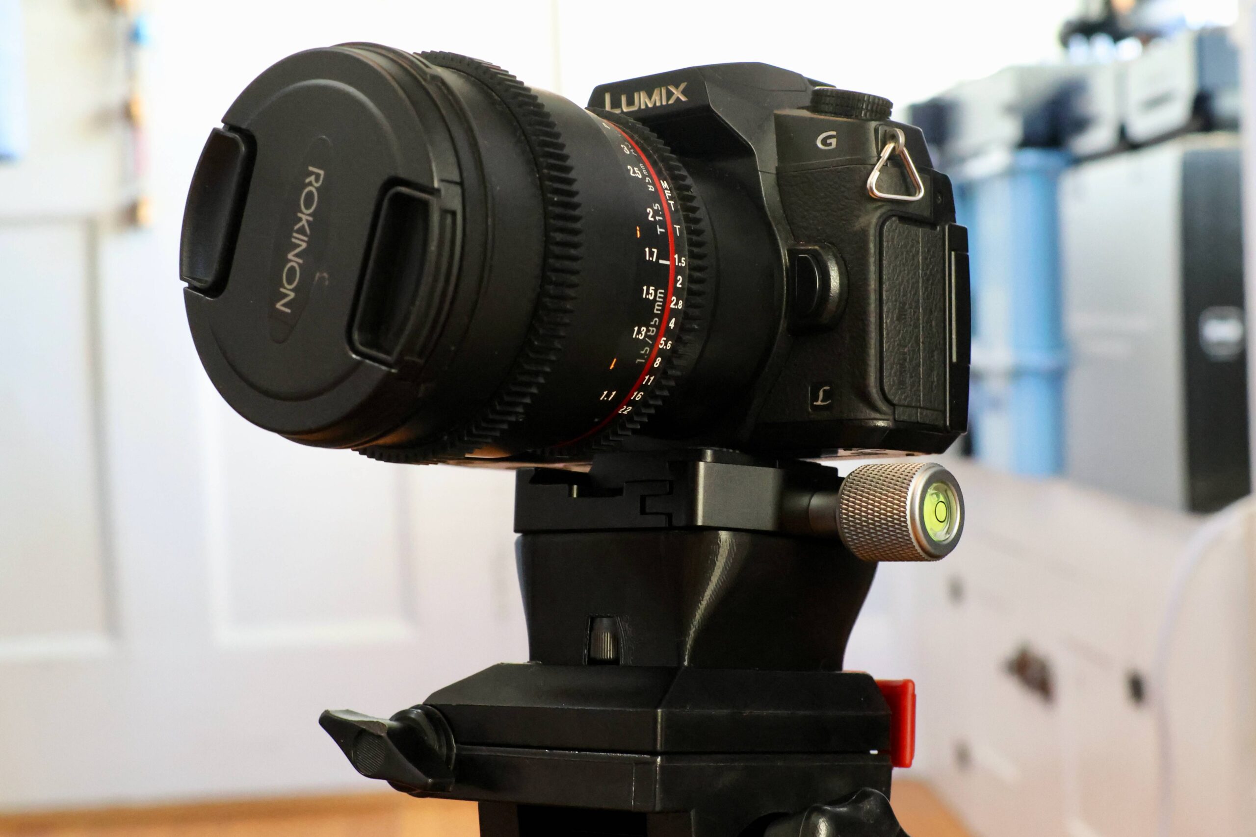
There are several semi-professional thrifters in my life that regularly rotate through the different Goodwill stores in our city prowling for deals. Their habit exposes me to a bit of second hand second hand shopping, and I always request camera equipment. Above is the current state of the tripod pile.
Often times these donated tripods don’t come fitted with their adapter plates for attaching to cameras. This nominally terminal condition is easily recoverable in the age of 3D printing.
My beloved blog post still sits on the throne as the most effective format for engineering projects. To me, Inlining code, photographs, CAD models and schematics in an interactive way trumps other mediums. This level of interactivity closes the gap between reader and material, allowing an independent relationship with the subject outside of the story being told by the author.
Working on stream to an online audience has a similar effect, the unedited and interactive format yielding a real understanding of the creators process and technique.
For a while there, I’d settled into a nice habit of broadcasting project development live on twitch. Two moves later, things have settled down enough in my personal life that I feel it’s time to try to get back into this habit.
Before we get started again, I took some time to improve the ergonomics (both hardware and software) of my stream setup. The following documents a few smaller projects, all in service of these upcoming broadcasts.
In collaboration with Won Pound for his forthcoming album release via minaret records I was recently commissioned to lead an expedition into latent space, encountering intelligences of my own haphazard creation.
A word of warning:
This and subsequent posts as well as the GitHub etc. should be considered toy projects. Development thus far has been results-oriented, with my git HEAD following the confusing and exciting. The goal was to make interesting artistic assets for Won’s release, with as little bandwidth as possible devoted to overthinking the engineering side. This is a fun role-reversal, typically the things that leave my studio look more like brushes than paintings. In publishing this work, the expected outcome is also inverted from my typical desire to share engineering techniques and methods; I hope my sharing the results shifts your perspective on the possible ways to bushwhack through latent space.
So, with that out of the way the following post is a summary of development progress thus far. Here’s a demo:
There are a few repositories associated with this work:
GANce, the tool that creates the output images seen throughout this post.
Pitraiture, the utility to capture portraits for training.
If you’re uninterested in the hardware/software configurations for image capture and GPU work, you should skip to Synthesizing Images.
So I’ve been working a lot in the past day in ironing out part of the night side loop (loop 3 in this diagram). Basically, it starts recording based on an input from a sensor and continues to record until these inputs stop occurring.
My test code looks like this
v1 = CameraModuleVideo("/home/pi/CreatureCapture/", "video1")

try:
	v1.startRecording()
except ValueError as e:
	print(e)

FilmDurationTrigger(5)

try:
	v1.stopRecording()
except ValueError as e:
	print(e)
The interesting functions at work here are the following:
def FilmDurationTrigger(time):
	t = CameraTimer(time)

	while True:
		continueFlag = False
		print "Filming For " + str(time) + " Seconds"
		t.run()
		while (t.isExpired() != True):
			if (GetContinueTrigger() == True):
				continueFlag = True
				print "Trigger Found, Continuing"
		print "Time Has Expired, Continue Flag Is Set To " + str(continueFlag)
		if (continueFlag == False):
			break
FilmDurationTrigger() Takes the period of time that will be filmed, in this example, it’s 5 seconds just to conserve time, but in application it will be 20 seconds. This code will pause for the input time, and continue to be paused upon inputs from GetContinueTrigger(). This delay allows the code to continue filming until there are no inputs.
In this example, GetContinueTrigger() returns a Boolean if a random event occurs, but in application it will return a Boolean based on the status of a motion detector.
def GetContinueTrigger():
	z = randint(0,10000)
	k = ((z == 115))
	return k
I ran two tests, both of them produced separate results. The first one created a 10 second long video:
pi@raspberrypi ~/CreatureCapture $ python CreatureCaptureTest2.py
Filming For 5 Seconds
Trigger Found, Continuing
Time Has Expired, Continue Flag Is Set To True
Filming For 5 Seconds
Time Has Expired, Continue Flag Is Set To False
Terminated
And the second created a 15 second long video:
pi@raspberrypi ~/CreatureCapture $ python CreatureCaptureTest2.py
Filming For 5 Seconds
Trigger Found, Continuing
Trigger Found, Continuing
Trigger Found, Continuing
Trigger Found, Continuing
Time Has Expired, Continue Flag Is Set To True
Filming For 5 Seconds
Trigger Found, Continuing
Time Has Expired, Continue Flag Is Set To True
Filming For 5 Seconds
Time Has Expired, Continue Flag Is Set To False
Terminated
These two test shows that variable capture length functionality works! As a note, the actual times on the output video varies from the amount of time that it’s designed to record for. This is because the variable frame rate nature of the video coming out of the camera module, it causes the videos to come out a little short, but they still contain all the frames of the amount of time desired to record, just scaled slightly by frame rate error.
One of the biggest problems with the built in commands for using the Raspberry Pi Camera module is that you can’t stop a recording after an unknown time. You can record for a given number of seconds and that’s it. I have attempted to solve this problem by backgrounding the initial record process with a time of 27777.8 hours (99999999 seconds) when it’s time to stop recording, the process is manually killed using pkill.
Here is a test of my code, which I’ve called CameraModulePlus (written in python) which takes two videos, one for five seconds, and one for ten seconds, with a 10 second delay in between.
from CameraModulePlus import CameraModuleVideo
import subprocess
from time import sleep
import time

v1 = CameraModuleVideo("/home/pi/CreatureCapture/", "video1")
v2 = CameraModuleVideo("/home/pi/CreatureCapture/", "video2")

try:
	v1.startRecording()
	time.sleep(5)
	v1.stopRecording()

	time.sleep(10)

	v2.startRecording()
	time.sleep(10)
	v2.stopRecording()

except ValueError as e:
	print(e)
Here is a result of the 5 second duration test:
Here is a result of the 10 second duration test:
As you can see, it works pretty good for how barbaric it is. The full class for CameraModuleVideo can be found here. In the future, I’d like to encode a lot more data into the CameraModuleVideo class, things about time etc. Also I would like to monitor available space on the device to make sure there is enough space to record.
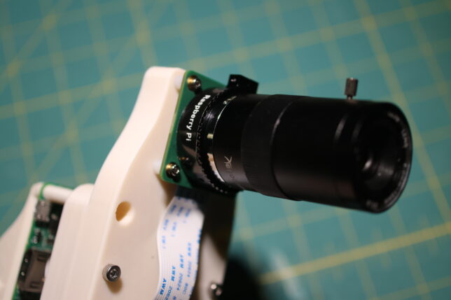
I’ve decided to embark on a video surveillance project! My family lives in a very rural part of the US, and constantly hear and see evidence of animals going crazy outside of my home at night. The goal of this project is to hopefully provide some kind of insight as to what animals actually live in my backyard.
Ideally, I want to monitor the yard using some kind if infrared motion detector. Upon a motion detection, an IR camera assisted by some IR spotlights would begin filming until it has been determined that there isn’t any more movement going on in yard. These clips would then be filed into a directory, and at the end of the night, they would be compiled and uploaded to YouTube. This video would then be sent to the user via email.
I’ve created the following flowchart to develop against as I begin implementing this idea.
I’ll be using a Raspberry Pi to implement this idea, a few months back I bought the IR camera module and haven’t used it for anything, this would be a good project to test it out.
There are a few hurtles that I’ll have to cross in order to make this project a success, like most groups of problems I deal with, they can be separated into hardware and software components.
Hardware
Minimize false positives by strategically arranging motion detectors
Make sure IR Spotlights are powerful enough to illuminate area
Enclosure must be weatherproof & blend in with environment, Maine winters are brutal.
Software
The Pi doesn’t have any built in software to take undetermined lengths of video.
Must have a lot of error catching and other good OO concepts in order to ensure a long runtime.
I’ve actually come up with a routine for solving the first software problem I’ve listed, hopefully I’ll have an example of my solution in action later tonight.
Ideally, this project will have a working implementation completed by May 21, which is 7 days from now.
I’ve worked very hard since my last update to move all of the hardware that interfaces the Raspberry Pi with the plants (GPIO, ADC etc) from on board the Raspberry Pi using the GIPO to a daughterboard based around an Arduino.
This has been a lot of work to accomplish, but as of about a week ago, the transition was completed in it’s entirety and everything is operating totally normally without using any GIPO on the Pi.
This provides a portability for the platform that I haven’t been able to achieve so far. As the name of the project suggests, I’ve only used a Raspberry Pi to drive all of the hardware so far as well as do everything with the software. This transition opens up the possibility of using any computer running linux to be able to drive a PiPlanter if they have the board.
One of the next steps that I take in this project would to be to design and fabricate PCB’s for specifically for this. This is certainly going to be a challenge for me, but it’s nothing I can’t handle. This also gives me the opportunity to maybe start selling PiPlanters which is exciting. I might need to change the name for obvious reasons…
Here are some nice photos of the updated setup:
All of the code and documentation for this version of the PiPlanter can be found here.
I am going on break from school from today, December 18th 2014 to on or around January 14th 2015. Now that the PiPlanter isn’t at my house, I can’t access the network remotely and make changes to the code. The next month will be a good stress test of the new daughterboard infrastructure. Hopefully it all goes well.
So in my last posting of the PiPlanter source code, the python script alone was 500 lines long. The intent with was to make things more modular and generic compared to the original version of the code that ran two years ago. Since the project has expanded a considerable amount since two summers ago, my goal of keeping everything short and concise isn’t really valid anymore so I’ve decided to split the code up into modules.
This improves a number of things, but it makes it kind of inconvenient to simply paste the full version of the source into a blog post. To remedy this, I’ll be utilizing www.esologic.com/source, something I made years ago to host things like fritzing schematics.
The newest publicly available source version can be found here: https://esologic.com/source/PiPlanter_2/ along with some documentation and schematics for each version to make sure everything can get set up properly. What do you think of this change? Will you miss the code updates in the body text of a blog post?
With all that out of the way, let’s talk about the actual changes I’ve made since the last post.
The first and foremost is that using Pillow, I’ve added a way to overlay text onto the timelapse frames like so:
This was prompted by some strange behavior by the plants I noticed recently seen here:
I thought it was strange how the chive seemed to wilt and then stand back up and then wilt again, it would have been nice to be able to see the conditions in the room to try and determine what caused this. Hopefully I can catch some more behavior like this in the future.
Here is the new Image function with the text overly part included if you’re curious:
Now that I’ve got the PIL as part of this project, I’ll most likely start doing other manipulations / evaluations to the images in the future.
Ten days ago I finished installing the third ever instance of the PiPlanter in a lab in the physics department at my college! I went with the the rack mounted design as I did this past summer, and am going to be growing Basil, Cilantro and Parsley as opposed to tomatoes. Here are some photos of the new setup:
There are a few major changes that come with this new instance. The first and foremost being the addition of LED grow lights. I’ll post a new version of the code with LED routines included when I think it’s polished enough. The second difference is that a tray of soil is being used as the growth medium for the plants as opposed to pots of soil. This will more than likely be the configuration I use moving forward. The final difference is the actual type of plants being grown. I’m moving away from tomatoes because there will be nothing to pollinate the flowers in the winter as well as the fact that I cook a lot and it will be neat to have spices that I can use on a day to day basis.
The first 10 days of growth has gone well. Here’s a video of them growing so far:
There are two parts of Arduino code, the sender and the receiver. The following code sends a sample piece of CAN data. Attach a potentiometer to A0, and twist it to see the differences in data in the receive code:
//Send CAN data

#include <mcp_can.h>
#include <SPI.h>

MCP_CAN CAN(10);                                      // Set CS to pin 10

void setup()
{
    Serial.begin(115200);

START_INIT:

    if(CAN_OK == CAN.begin(CAN_500KBPS))                   // init can bus : baudrate = 500k
    {
        Serial.println("CAN BUS Shield init ok!");
    }
    else
    {
        Serial.println("CAN BUS Shield init fail");
        Serial.println("Init CAN BUS Shield again");
        delay(100);
        goto START_INIT;
    }
}

void loop() {
    // send data:  id = 0x00, standrad flame, data len = 8, stmp: data buf

    unsigned char stmp[8] = {map(analogRead(0),0,1024,0,255), 1, 2, 3, 4, 5, 6, 7};

    CAN.sendMsgBuf(0x00, 0, 8, stmp);
    delay(100);                       // send data per 100ms
}
The following prints all CAN data received to the serial monitor:
//Receive CAN data

#include <SPI.h>
#include "mcp_can.h"

unsigned char Flag_Recv = 0;
unsigned char len = 0;
unsigned char buf[8];
char str[20];

MCP_CAN CAN(10);                                            // Set CS to pin 10

void setup()
{
    Serial.begin(115200);

START_INIT:

    if(CAN_OK == CAN.begin(CAN_500KBPS))                   // init can bus : baudrate = 500k
    {
        Serial.println("CAN BUS Shield init ok!");
    }
    else
    {
        Serial.println("CAN BUS Shield init fail");
        Serial.println("Init CAN BUS Shield again");
        delay(100);
        goto START_INIT;
    }
}

void loop()
{
    if(CAN_MSGAVAIL == CAN.checkReceive())            // check if data coming
    {
        CAN.readMsgBuf(&len, buf);    // read data,  len: data length, buf: data buf

        Serial.print("ID: ");

        Serial.print(CAN.getCanId());

       Serial.print(" / ");

        for(int i = 0; i<len; i++)    // print the data
        {
            Serial.print(buf[i]);
            Serial.print(",");
        }
        Serial.println();
    }
}
Twist the potentiometer and see the change in data to see that it’s all working: