Recycling an Old Friend

This post first appeared on Patreon.

There’s a triple-point energy to working on something out at the edge of your abilities. Enumerated alongside the possibilities for failure are visions of the finished piece, installed and gloriously humming along, that make the long nights ahead less intimidating.

In late October of 2018, I began the CAD for such a project. Telapush had just closed our largest deal to date. We were to contracted to build a massive illuminated sign that would map social media interactions to custom animations to be displayed in real time. The piece was to run, un-attended for the entire month of December in the Center Court of the Prudential Center mall, inside of Boston’s most distinctive skyscraper.

Erin and I had been pouring effort into Telapush for some time, and this installation was to be the largest tangible result from that effort. Serious people spending real money and expecting actual results. Boston was my new home and I felt that this project was my chance to make a good first impression to this new and intimidating place. This heightened importance, paired with the reverence for the challenge, coaxed out some good engineering; the project was a rousing success. More details about this installation can be found in my portfolio entry on the project.

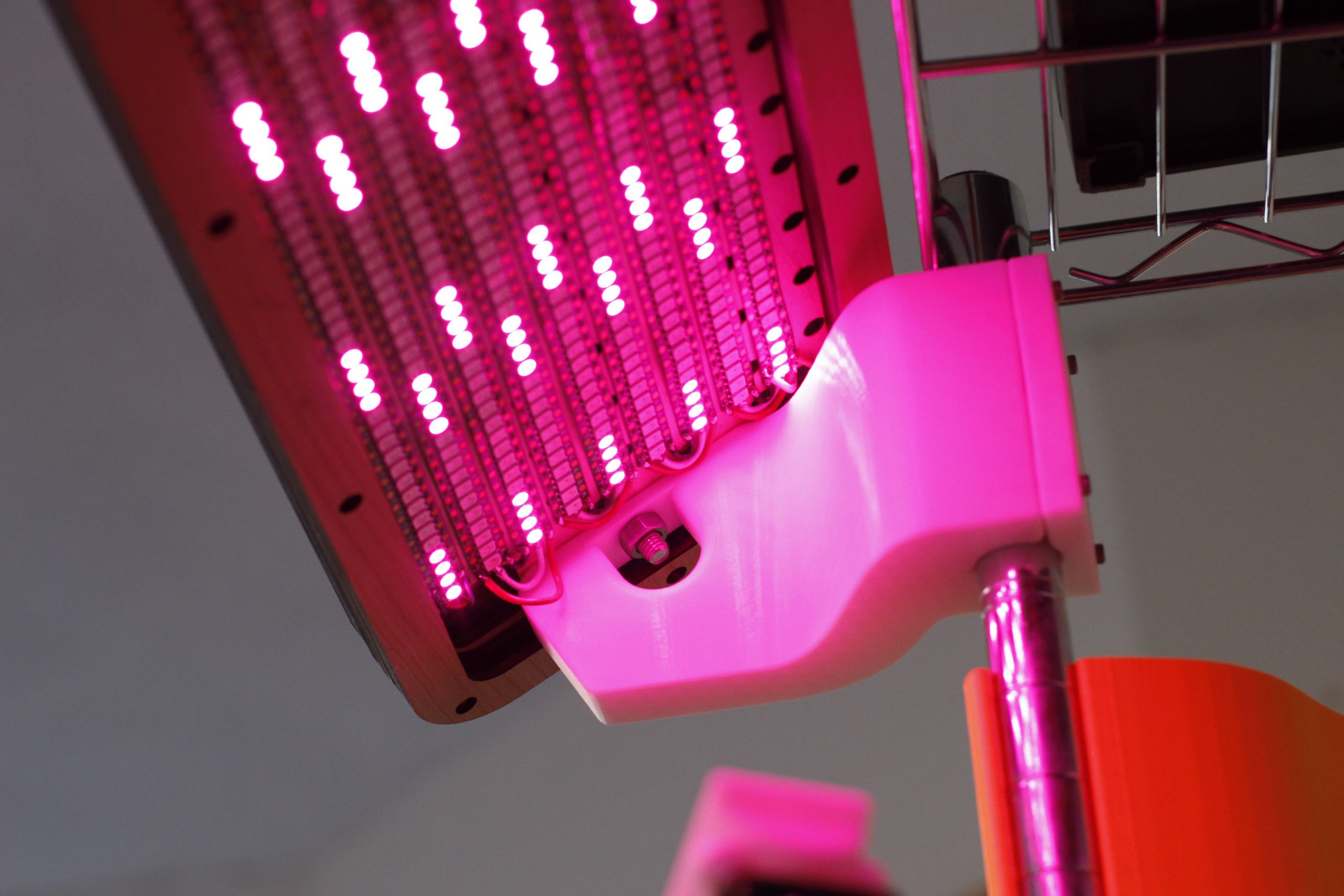
Luckily, one element of the installation that I was able to retain possession of after the installation concluded was the LED matrix. An overwhelming array of 1215 addressable LEDs, and a 100W power supply to drive them.

Still brimming with usefulness, and valuable as a totem commemorating the successful project, the light bar was filed into storage. Unfortunately, I lacked the bandwidth and inspiration to pick it back up. In the past few months however, on quiet nights, I could hear it calling out to me from the crawlspace, pleading to be reanimated. And after a few years of rest, this post describes how this favorite project is given a new lease on life to enhance my 3D printing workflow.

Continue reading →

The Silent Dripper

The first revision of this project was shipped in November of 2020, but the subsequent redesign was commissioned and completed the following summer in 2021. This post primarily a journey through that second revision, and it’s publication comes some time after the deliverable was shipped to the client.

Engineering requirements that arrive downstream from artistic intent are my favorite constraints to work inside of. It forces the engineer to assume the role of the artist, considering the feelings and ideas that will be communicated to the audience with the piece. The engineer also has to become an audience member to understand other factors about how viewing will take place, if the environment will change such that the piece needs to respond in kind. The space in between these to roles needs to be projected into the standard space of product requirements, weights, tolerances, latencies etc. that are common in the profession.

As a part of my freelance practice, interdisciplinary artist Sara Dittrich and I recently collaborated on a series of projects, adding to our shared body of work. The most technically challenging part of these most recent works was a component of her piece called The Tender Interval. I urge you to go read her documentation on this project, there is a great video overview as well.

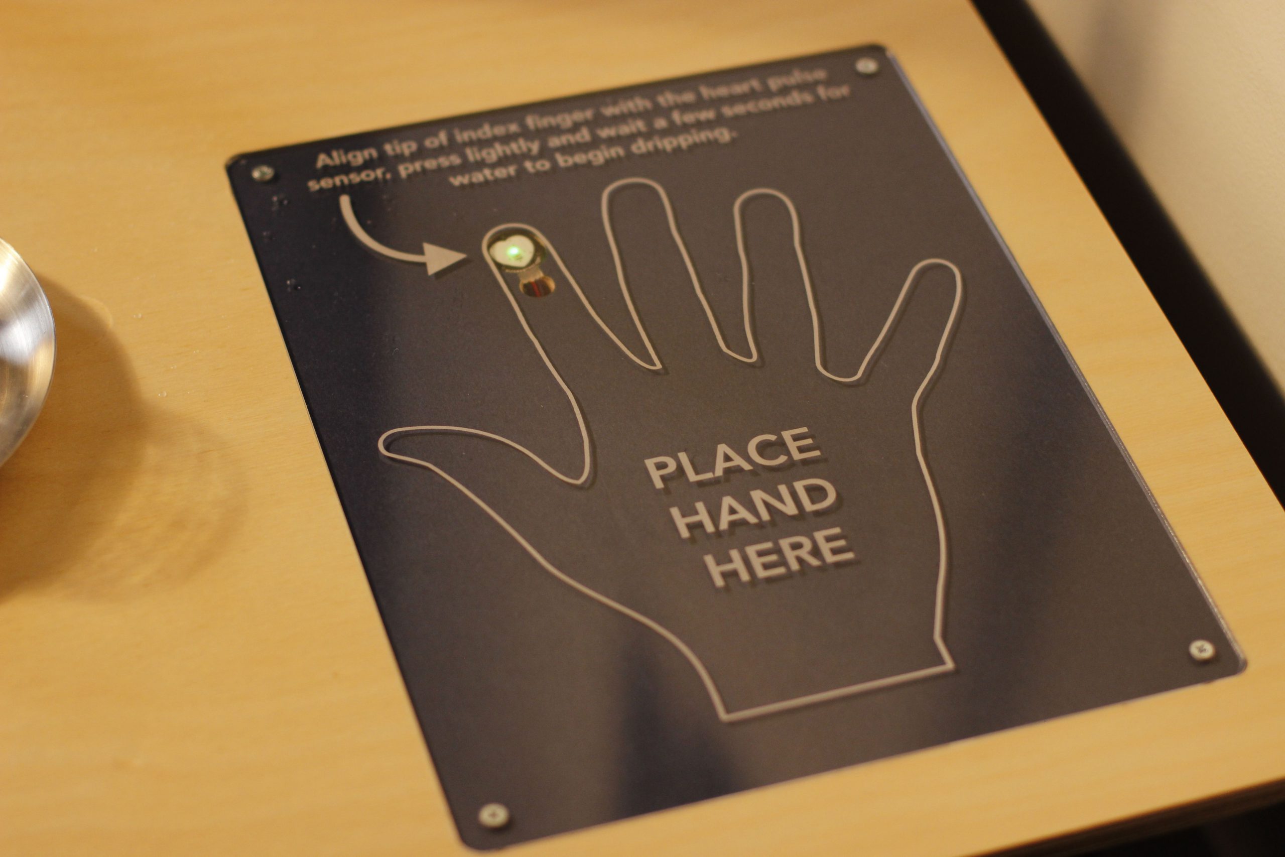
Two performers sit at a table across from each other, above them is an IV stand with two containers full of water. Embedded in the table are two fingerprint sensors, one for each of the people seated at the table. Performers place their hands on the table, with their index fingers covering the sensors. Each time their heart beats, their container emits a single drop of water, which falls from above them into a glass placed next to them on the table. Once their glass fills, they drink the water. Optionally, virtual viewers on twitch can take the place of the second performer by sending commands on twitch that deposit water droplets into the second glass.

Design and manufacture of table and this insert were completed by Sara Dittrich

The device responsible for creating the water droplets (the dripper) ended up being a very technically demanding object to create. The preeminent cause of this difficulty was the requirement that it operate in complete silence. Since the first showings of this piece were done virtually due to the pandemic, we were able to punt this problem and get the around noisy operating levels of V1 using strategic microphone placement. However, this piece would eventually be shown in a gallery setting, which would require totally silent operation.

The following is a feature overview and demonstration of the completed silent dripper:

If you’re interested in building one of these to add to your own projects, there is a github organization that contains the:

Per usual, please send along photos of rebuilds of this project. Submit PRs if you have improvements, or open issues if your run into problems along the way.

The rest of this post will be a deep dive into earlier iterations of this project, and an closer look at the design details and challenges of the final design. It’s easier to understand why a second iteration was needed after reviewing the shortcomings of version 1, so that’s where we’ll start.

Continue reading →

BlinkBox – A test tool for addressable LED development

This project got featured on the official arduino blog as well as hackaday! Thanks to everyone that shared!

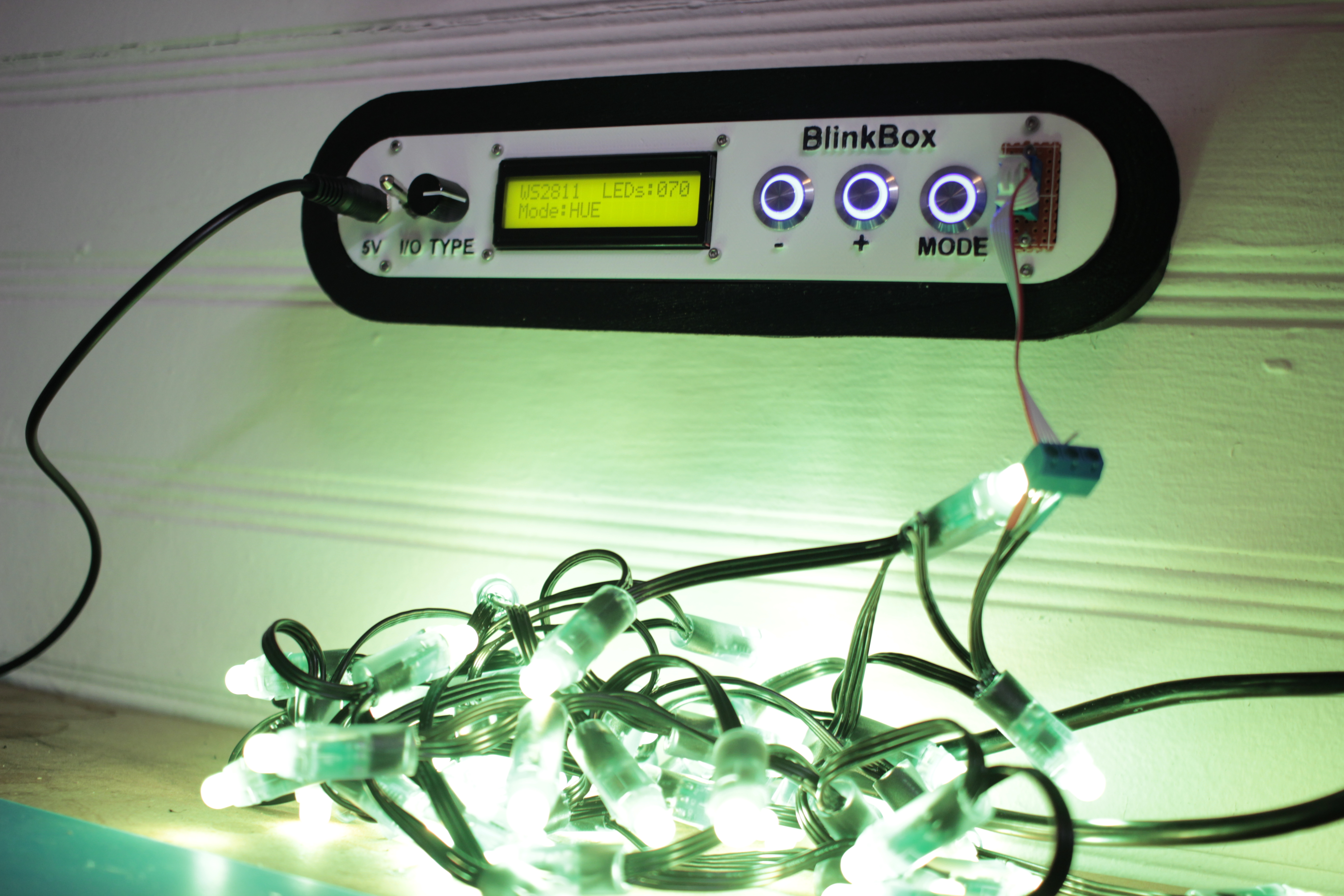
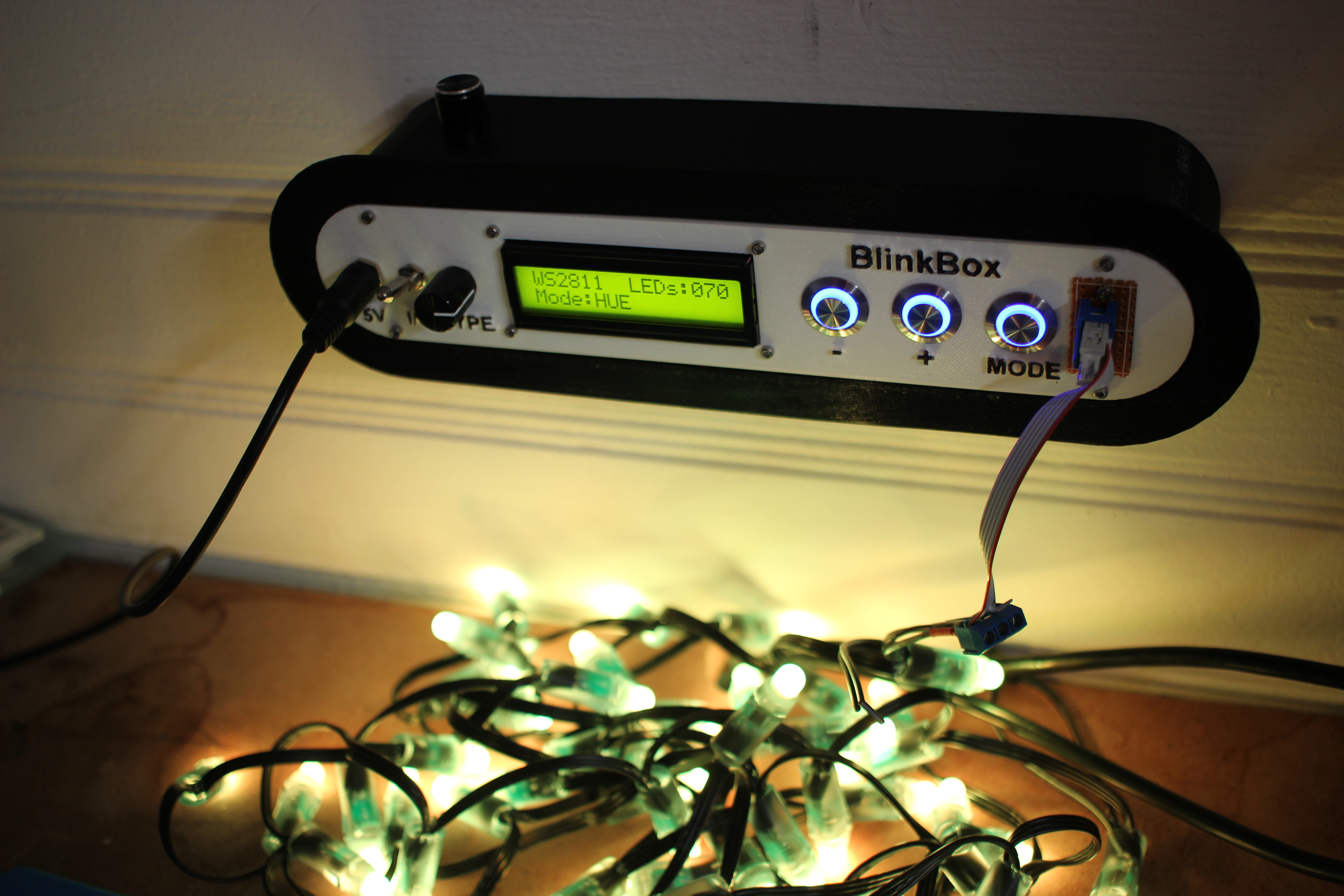
I work with addressable LEDs a lot. For all that they’re great for, they’re kind of hard to debug when you have a lot of them connected up at once. This is especially apparent when you have many small single modules in hard to reach spaces.

Here’s my solution:

This lets me set the color and number of LEDs in a strip, and then displays a color pattern. This way I can tell if an LED has become disconnected in a strip, or if a channel  inside a particular has died.

Features

  • Select LED type with the type switch, 4 positions
  • Can test up to 400 LEDs at a time, if you can find a worthy power supply
  • 3 Test modes
    • RGB – 1 second red, 1 second green, 1 second blue
    • HUE – Lock strip at HSV (x, 255, 255) and x loops from 0-255
    • WHTE – Set the strip to RGB(255, 255, 255)
  • Count and Mode are saved into eeprom, so you don’t have to keep resetting the strip if it powers off
  • Wall mount fittings

Design Explanation

All of the raw code solidworks, and KiCAD have been posted on my github. You can look at the 3D models on thingiverse as well.

Mechanical

Here are a couple of quick renders of the assembly design:

The screw mount behind the pushbuttons is extended to be able to support the pressure without flexing:
I added a ridge so you can grab onto something as you interact with the switches / buttons.

Electronics

Here’s the circuit:

There really isn’t a lot going on here, the parts are probably the coolest part of the project. The 5V jack is a 6mm DC barrel jack, the pushbuttons are illuminated 16mm pushbuttons from adafruit,  the on/off switch is a locking toggle switch, and the 4 position rotary switch can be found here.

I wired up the circuit on a spare piece of perfboard.

Software

My code is available on my github.

The LED driving part of the code is based on FastLED, a beautiful library for driving these types of addressable LEDs.

The rest of the code is mostly just a hardware UI problem, and isn’t all that interesting. LED count “ramps” as you hold the button down. The longer you hold the button, the faster the

Wrap up

That’s pretty much it! I’ve already gotten some use out of this tool and have found great satisfaction in taking the time to make it look nice as it will be a permanent addition to my lab.

I’ll post any updates I make to this project as edits to the top of this post.

Thanks for reading, and here are a few more photos:

Multiple Frequency Counter for Arduino

Ever wanted to measure the frequency of a square wave using an Arduino? There are a couple of good solutions out of there to do this, but not all of them had the capacity to do multiple inputs. I couldn’t find this quickly so here is my solution.

Here’s the link to the code if you want to skip ahead. The code uses interrupts and doesn’t use any kind of delaying so it’s good for giant state-machine applications. My application for this is measuring signals from 10Hz-100Hz in which this can measure within 1% error. The absolute limits of the code are 1Hz-50KHz.

This project is on GitHub if you want to send a pull request to make improvements.

Setup

For testing, I wrote a simple function generator and uploaded it to a separate arduino. It outputs a pulse train with periods of 10ms (100Hz) and 5ms (200Hz) on pins 2 and 3. I attached LEDs and their resistors for debugging.

Pins 2 and 3 on the function generator to pins 2 and 3 on the frequency counter.
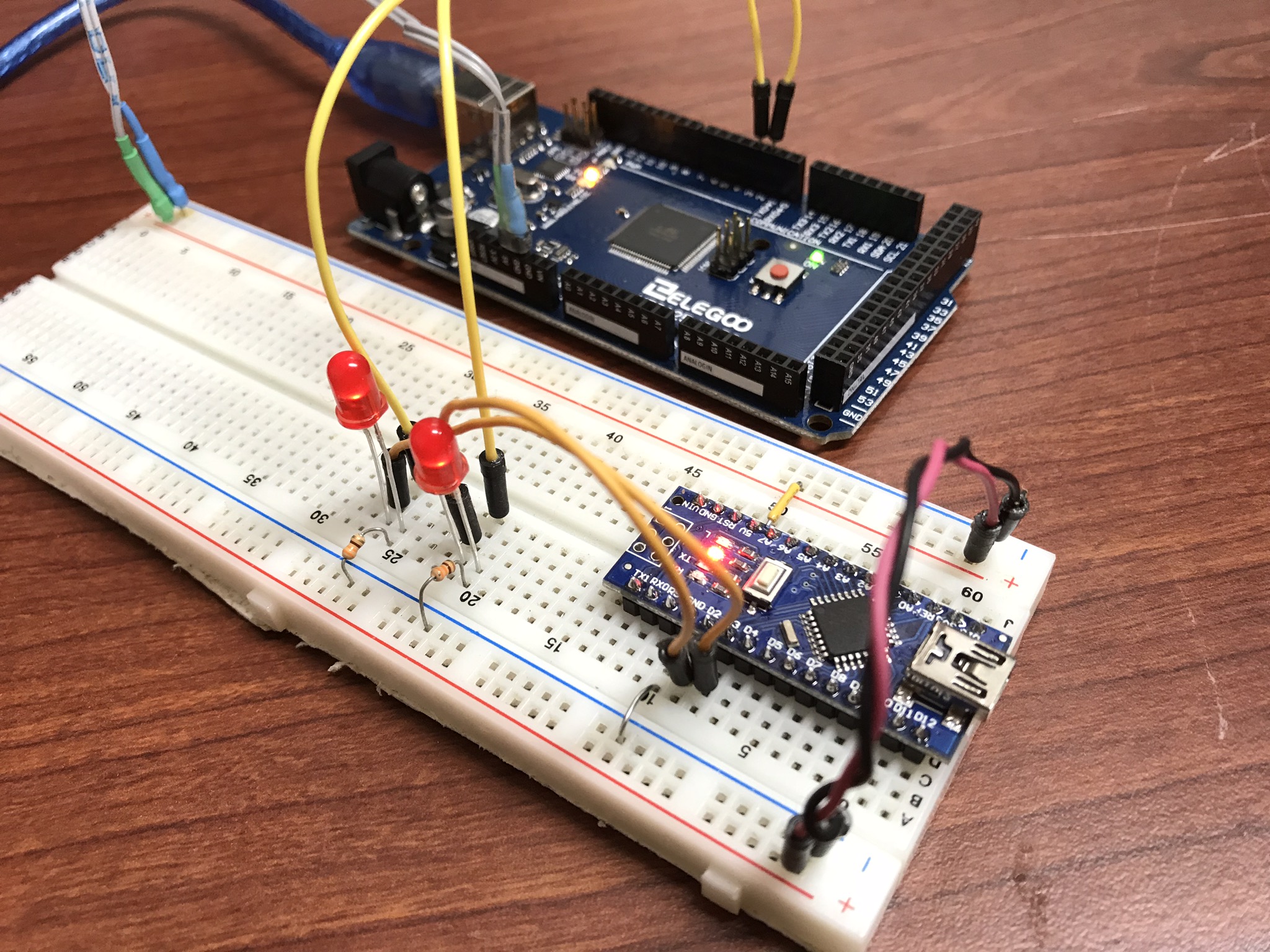
setup

The code for this simple function generator is here:

/*
 * 3/29/2018 - Devon Bray - https://www.esologic.commultiple-frequency-counter-arduino/
 */


int pin_100Hz = 2;
int pin_200Hz = 3;

unsigned long previous_time_100Hz;
unsigned long previous_time_200Hz;

void setup() {
  pinMode(pin_100Hz, OUTPUT);
  pinMode(pin_200Hz, OUTPUT);
}

void loop() {

  unsigned long current_time = millis();

  if ( (current_time - previous_time_200Hz) >= 5) {
    digitalWrite(pin_200Hz, HIGH);
    delayMicroseconds(1000);
    digitalWrite(pin_200Hz, LOW);
    previous_time_200Hz = current_time;
  }

  if ( (current_time - previous_time_100Hz) >= 10) {
    digitalWrite(pin_100Hz, HIGH);
    delayMicroseconds(1000);
    digitalWrite(pin_100Hz, LOW);
    previous_time_100Hz = current_time;
  }
  
}

Frequency Counter

This code will work fine in a stateless application, because there are no delay statements (which some other frequency counters I’ve seen online use). It’s a little bit complicated, send me a pull request if you can refactor it to be cleaner.

Here’s the sketch:

/*
 * 3/29/2018 - Devon Bray - https://www.esologic.commultiple-frequency-counter-arduino/
 * 
 * I've written most of the important notes as comments in the source, but a couple more details:
 * 
 * - The important data is stored in `period_averages_ms` and `frequency_averages_hz`. You address them using the indices defined at the top of the file. These arrays get updated each time `compute_counts()` is called. Keep it `compute_counts()` somewhere in the main() loop. 
 * 
 * - You could easily add more frequencies, you just have to `NUMSIGS`, make a specific ISR, and another `attachInterrupt` line in setup()
 * 
 * - It uses [interrupts](https://playground.arduino.cc/Code/Interrupts) which might not be right for your proejct, but normally shouldn't get in the way of too much stuff.
 * 
 * - If the ISR hasn't seen a new edge in 1000000us, both `period_averages_ms[p_index]` and `frequency_averages_hz[p_index]` will be set to zero!
 * - This means that slowest frequency that this code can detect is 1hz!
 * 
 */

int freq_pin_1 = 2; // the pin connected to the first signal, must be an interrupt pin! See the arduino docs
int freq_pin_2 = 3; // the pin connected to the second signal, must be an interrupt pin! See the arduino docs

#define BUFFSIZE 100 // a rolling average of the frequency/period is computed, and this is the size of that buffer

#define NUMSIGS 2
#define FREQ1INDEX 0
#define FREQ2INDEX 1

volatile int period_buffer_indices[NUMSIGS] = { 0 }; // the location of the index for adding to the rolling buffer average
volatile unsigned long period_buffers[NUMSIGS][BUFFSIZE] = { 0 }; // the buffers
volatile unsigned long previous_edge_times_us[NUMSIGS] = { 0 }; // the time that the previous edge came in in microseconds
volatile float period_averages_ms[NUMSIGS] = { 0 }; // the period time of a given signal in milliseconds
volatile float frequency_averages_hz[NUMSIGS] = { 0 }; // the frequency of a given signal in hertz
volatile bool period_buffer_locked[NUMSIGS] = { false }; // spin locks for the different buffers

void setup() {
  
  Serial.begin(9600);

  // the pins must be mapped to their ISRs 

  pinMode(freq_pin_1, INPUT_PULLUP);
  attachInterrupt(digitalPinToInterrupt(freq_pin_1), new_freq1_edge, RISING); // you could change this mode to whatever you were looking for, FALLING, CHANGE etc.

  pinMode(freq_pin_2, INPUT_PULLUP);
  attachInterrupt(digitalPinToInterrupt(freq_pin_2), new_freq2_edge, RISING);
}

void loop() {

  compute_counts();
  
  Serial.print("Pin 1: ");
  Serial.print(period_averages_ms[FREQ1INDEX]);
  Serial.print("ms, ");
  Serial.print(frequency_averages_hz[FREQ1INDEX]);
  Serial.print(" hz");
  
  Serial.print(" - Pin 2: ");
  Serial.print(period_averages_ms[FREQ2INDEX]);
  Serial.print("ms, ");
  Serial.print(frequency_averages_hz[FREQ2INDEX]);
  Serial.print(" hz");
  Serial.println("");  
}

void compute_counts() {

  // computes the average of the buffer for a given signal. Must be called before using the period_averages_ms or frequency_averages_hz buffers.
  
  for (int p_index = 0; p_index < NUMSIGS; p_index++) {
  
    float buffer_sum = 0;

    while (period_buffer_locked[p_index]) {}; // wait around for the ISR to finish
    
    period_buffer_locked[p_index] = true; // ISR won't add new data to `period_buffers`
    if ((micros() - previous_edge_times_us[p_index]) < 1000000) {
      for (int j = 0; j < BUFFSIZE; j++) {
        buffer_sum += period_buffers[p_index][j];
      }
    }
    period_buffer_locked[p_index] = false; // ISR will now add new data to `period_buffers`
    
    if (buffer_sum > 0){
      period_averages_ms[p_index] = ((buffer_sum / (float)BUFFSIZE)) / 1000;
      frequency_averages_hz[p_index] = (1 / period_averages_ms[p_index]) * 1000;  
    } 
    else {
      period_averages_ms[p_index] = 0;
      frequency_averages_hz[p_index] = 0;
    }
        
  }
}

void new_edge(int period_index) {

  unsigned long current = micros();

  if (period_buffer_locked[period_index] == false) { // if compute_counts is using the buffer, skip adding to it because that process isn't atomic

    period_buffer_locked[period_index] = true;
    
    period_buffers[period_index][period_buffer_indices[period_index]] = current - previous_edge_times_us[period_index];

    period_buffer_locked[period_index] = false;
    
    period_buffer_indices[period_index]++;
    if (period_buffer_indices[period_index] >= BUFFSIZE) {
      period_buffer_indices[period_index] = 0; 
    }  
  }
  
  previous_edge_times_us[period_index] = current; // but make sure the new time is set because this operation is atomic
  
}

void new_freq1_edge() {
  new_edge(FREQ1INDEX);
}

void new_freq2_edge() {
  new_edge(FREQ2INDEX);
}

I’ve written most of the important notes as comments in the source, but a couple more details:

  • The important data is stored in `period_averages_ms` and `frequency_averages_hz`. You address them using the indices defined at the top of the file. Make sure you call `compute_counts()`  before using this data. Keep it somewhere in main().
  • You could easily add more frequencies, you just have to `NUMSIGS`, make a specific ISR, and another `attachInterrupt` line in setup()
  • It uses interrupts which might not be right for your proejct, but normally shouldn’t get in the way of too much stuff.
  • If the ISR hasn’t seen a new edge in 1000000us, both period_averages_ms[p_index] and frequency_averages_hz[p_index] will be set to zero! This means that slowest frequency that this code can detect is 1Hz!

If you have any questions on how to add more signals, leave a comment!

Results

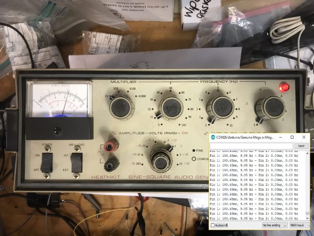
Here’s the output in the serial monitor attached to my function generator from earlier:
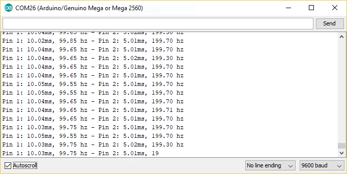
result

That’s like less than 1% error! Pretty good!

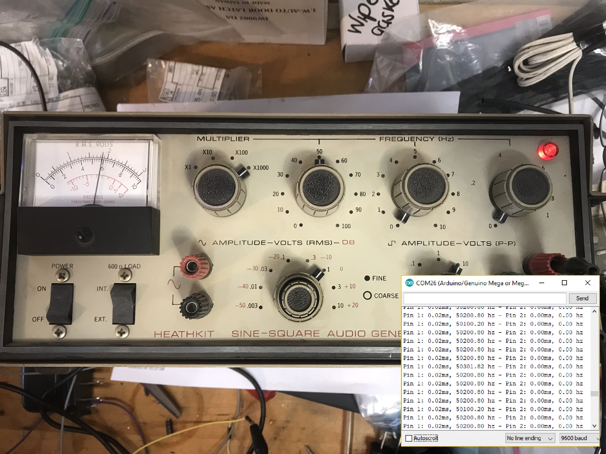
I also tested the code with a real function generator. Things worked really well until around 50KHz, so I would say that this code can’t be trusted past 50KHz.

10 Hz
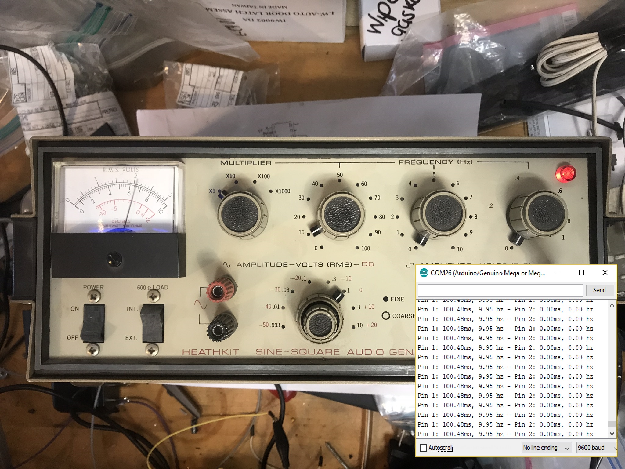
50 KHz
Thanks for reading!

Raspberry Pi Wire Shelf Mount + Wallet & Keys Hold + Spool Hook

Here’s a video:

For a while I’ve been logging my favorite prints here but some of them are two small to warrant a post. So introducing: #goodprints! At first I’m going to shoot for monthly installments, but as I print more, I’ll post more.

This time we’ve got 3 prints in the above video. Here are the details:

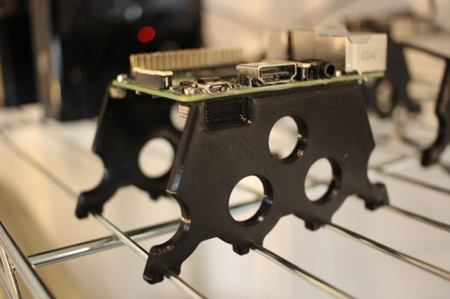
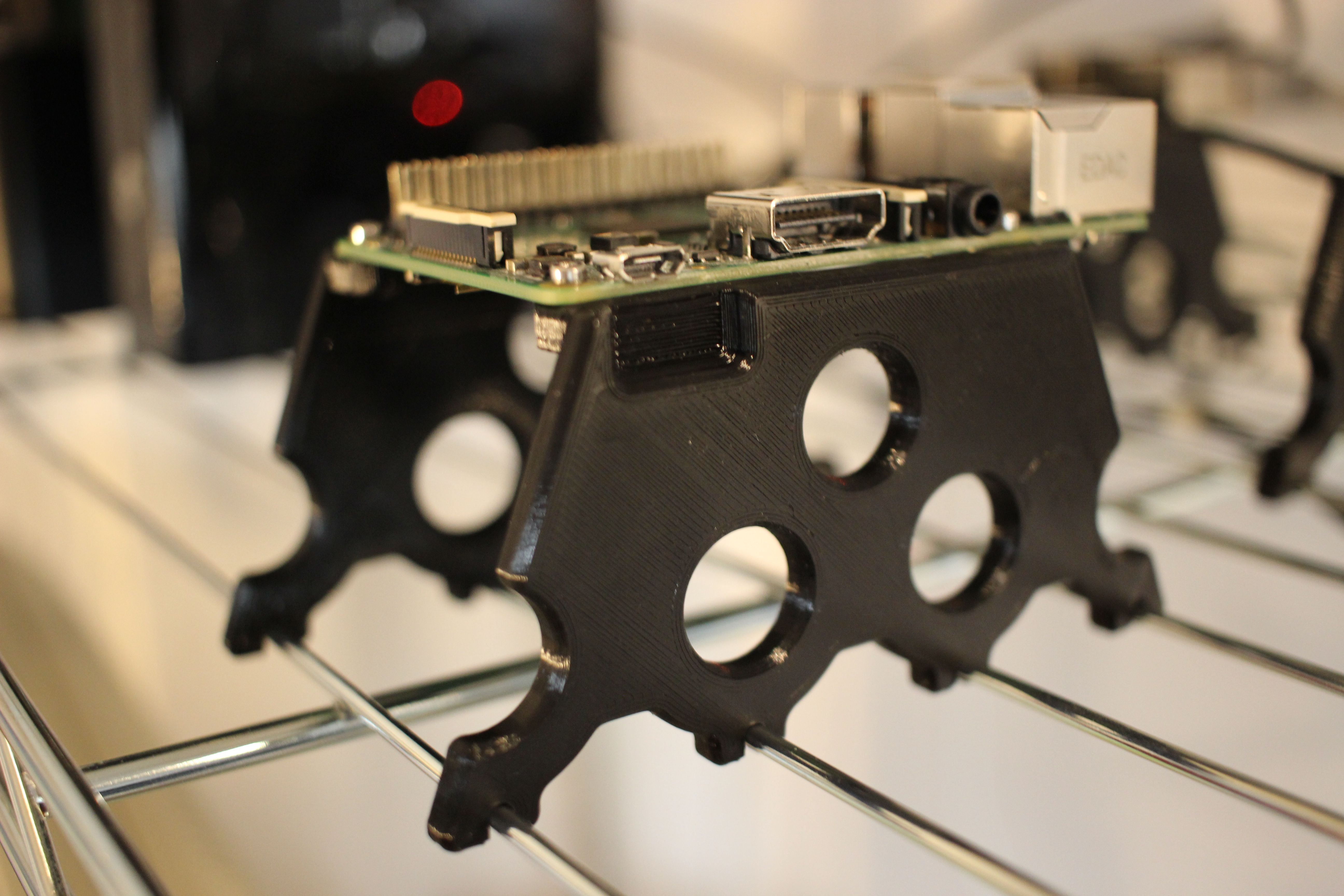
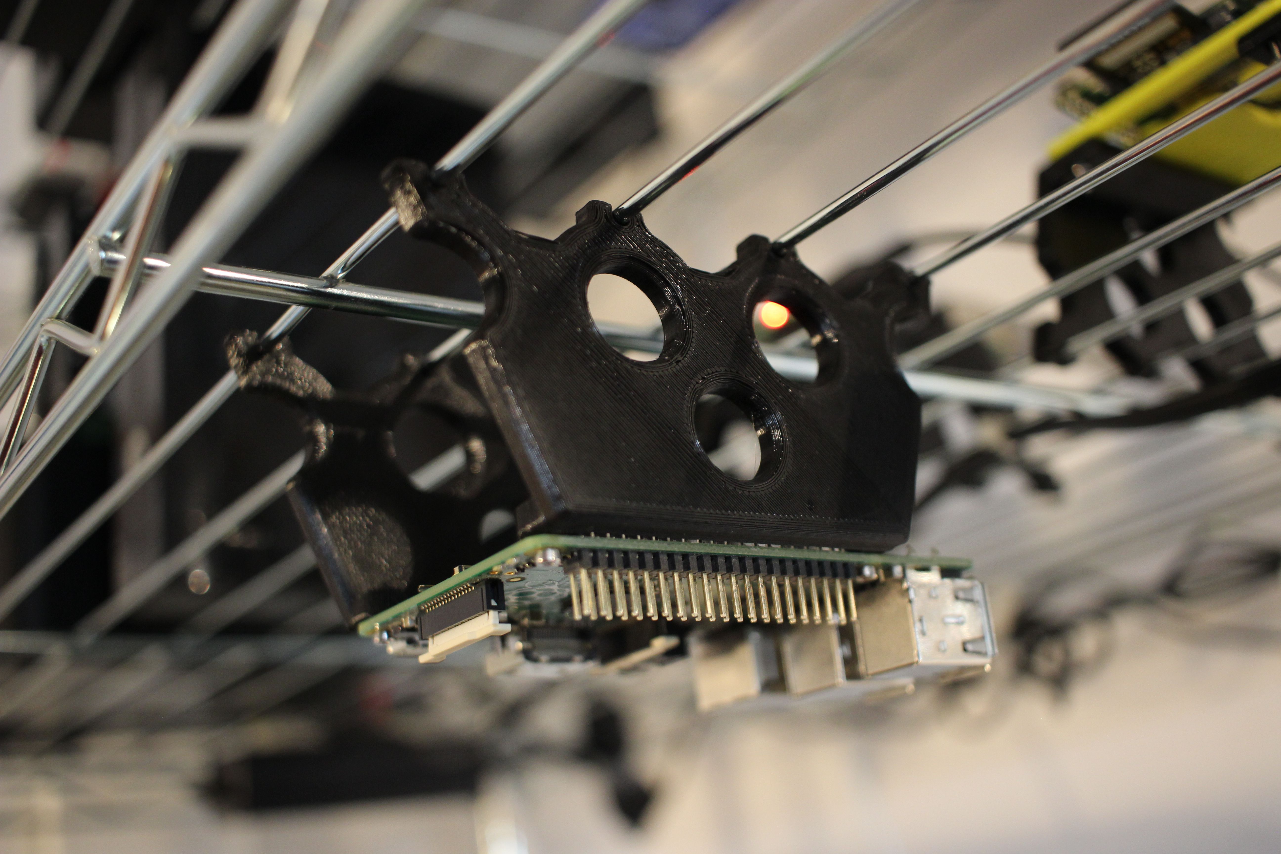
Raspberry Pi Wire Shelf Mount – Everyone knows that wire shelves are the best. Now you can securely mount a Raspberry Pi to one. Thingiverse Link

Here is the drawing for mating with the shelf:

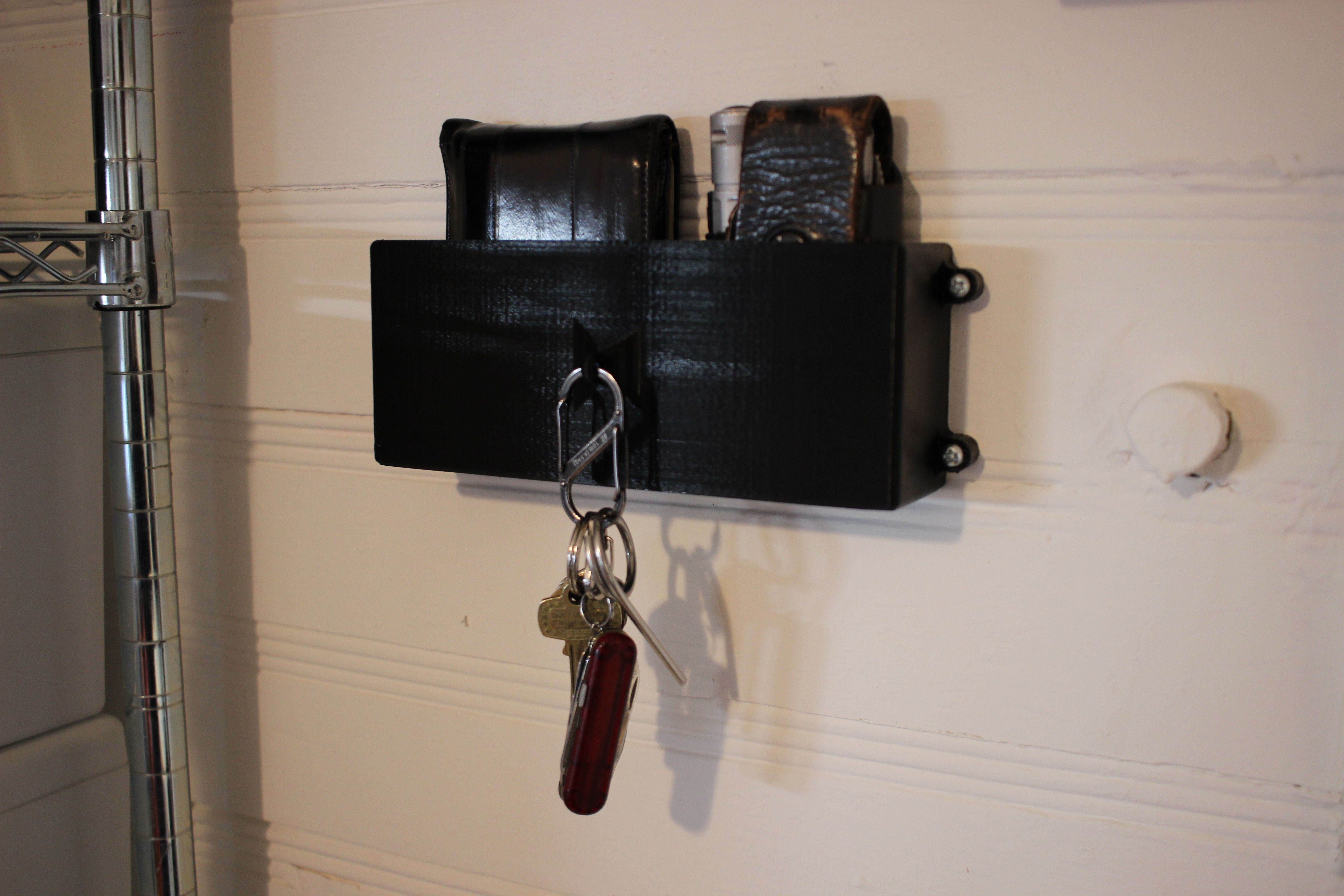
Wallet, Keys & Leatherman Wall Mount – I’m constantly loosing these things in my lab, now they’re not going anywhere. Thingiverse Link


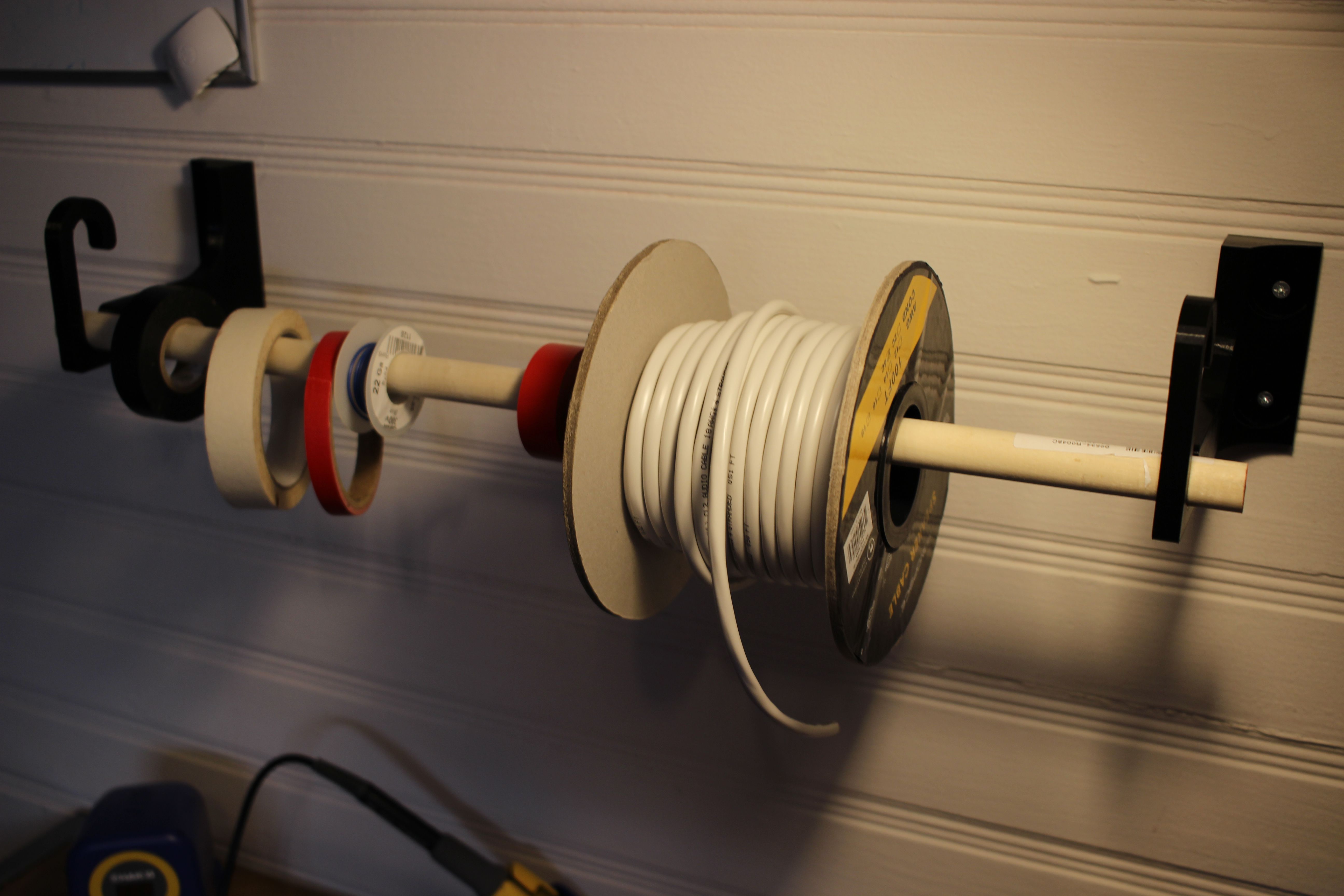
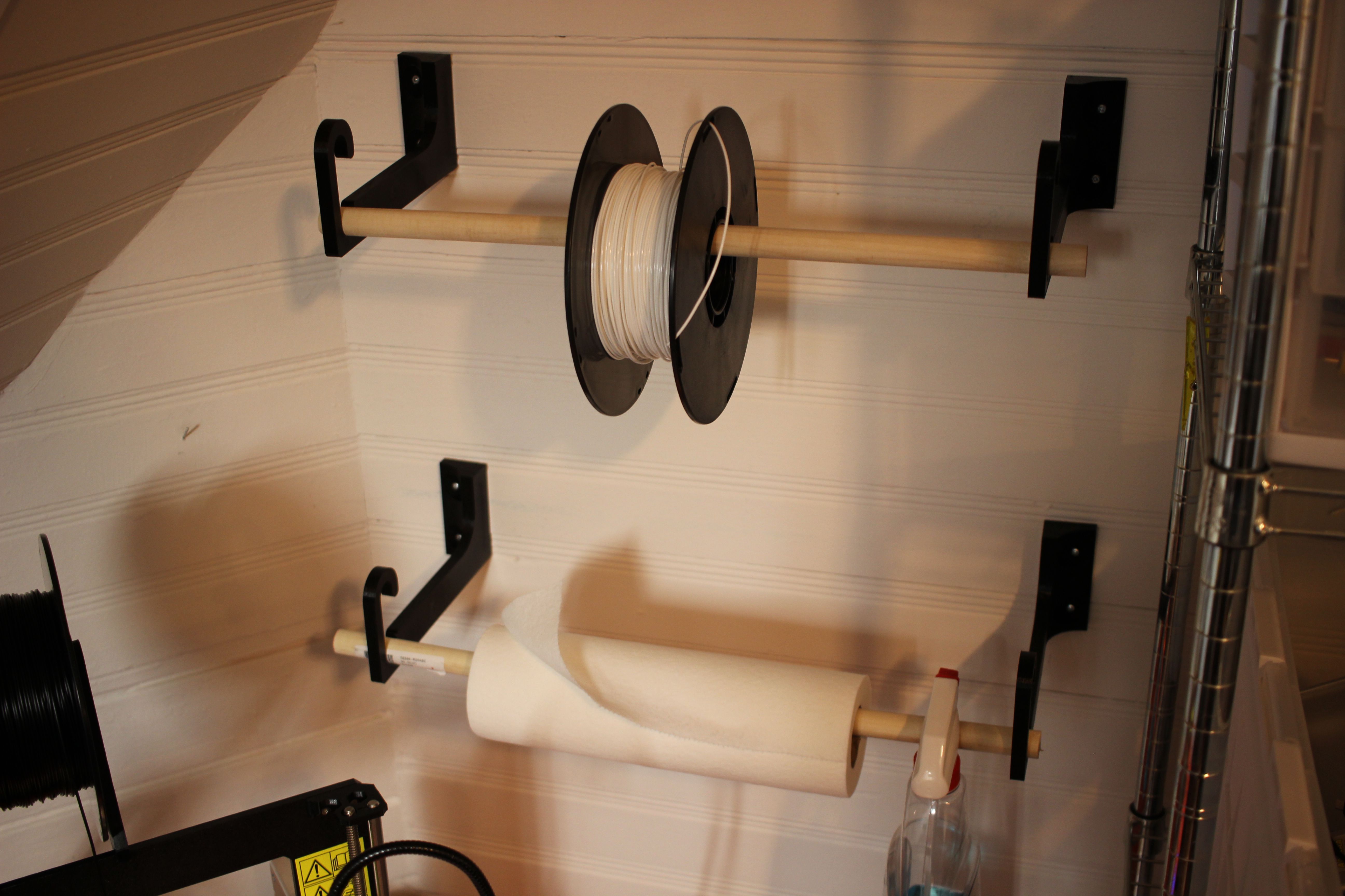
Wall Hook – This is for mounting stuff like filament spools, wire, and tape to the wall. It accepts 3/4 inch dowels. There are two version, one 85mm long and one 150mm long (designed to fit hatchbox 1kg filament spools). Thingiverse Link

CHAMP: Compliant Hook Arboreal Mobility Platform (Senior Thesis Project)

For my senior thesis project at WPI, myself and two colleagues (Rachael Putnam – RBE/ME and Mead Landis – RBE/ME) designed a tree climbing robot. I was in charge of designing and implementing the electronics and controls software. I was the most intense project I have ever worked on, both in terms of difficulty and potential impact. Here is our poster for project presentation day:

Here’s a video of the prototype climbing:

We did a blog during the project, here is the best post I wrote:

The report is massive, check it out here: https://digital.wpi.edu/concern/student_works/s4655j16f?locale=en


Soft-latching toggle switch with active reset circuit

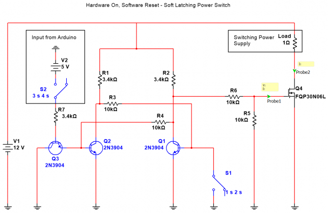
This circuit aims to replace a traditional toggle switch for switching large amounts of current. Instead of the bulky and expensive traditional toggle switch, this circuit allows for a cheap pushbutton, and a few transistors and resistors to be used and have the same effect.

For my application, I wanted a way to have the circuit draw very little curren
t when in the off state, be able to be powered on with a pushbutton, and then turned off through software on the Arduino.
Here is the circuit diagram:

Here’s a video of the circuit in operation:

The code running on the Arduino is very simple:

int button = 3;
int led = 2;

void setup() {
  pinMode(button, INPUT);
  pinMode(led, OUTPUT);

  digitalWrite(led, LOW);
}

void loop() {
  if (digitalRead(button)) {
    digitalWrite(led, HIGH);
  }
}

RS485 Hardware Network 2 – Multi-Byte Communication

Edit: I don’t really make a point of saying it, but the common ground between the modules isn’t necessary.

Here’s a video of the software running on the boards.

So for this example,  there are 4 bytes being transmitted from the master to the slaves.

  1. Start of Transmission (0xDB)
  2. ID of the slave to talk to
  3. The type of command
  4. The data that is transmitted

A transmission to set the pwm value of the green led on the slave with the ID 1 to 100 would be:

0xDB 0x01 0x01 0x64

This is the schematic of the circuit for this example:

This is the code running on the master Arduino:

#include <SoftwareSerial.h>

int MAX485_Receiver_Output_PIN = 10;
int MAX485_Driver_Input_PIN = 11;
int MAX485_Driver_Output_Enable_PIN = 12;

#define NUMSWITCHES 3

int ID_switches[NUMSWITCHES] = {2, 3, 4};
int mode_switch = 5; 

byte IDs[NUMSWITCHES] = {1, 2, 3};

#define TXSIZE 4

SoftwareSerial software_serial (MAX485_Receiver_Output_PIN, MAX485_Driver_Input_PIN); // RX, TX

byte target_node_ID;

struct transmission {

  byte start = 0xDB;
  
  byte ID;
  byte type;
  byte message;

  const int tx_size = TXSIZE;
};

void setup()
{
  software_serial.begin(9600); // begin software serial
  
  pinMode(MAX485_Driver_Output_Enable_PIN, OUTPUT);
  digitalWrite(MAX485_Driver_Output_Enable_PIN, HIGH); // this disables Receiver Output Enable and enables Driver Output Enable
  
  for (int index = 0; index < NUMSWITCHES; index++)
  {
    pinMode(ID_switches[index], INPUT); 
  }
  
  pinMode(mode_switch, INPUT);
  
  target_node_ID = 0;
}

void loop()
{
  for (int index = 0; index < NUMSWITCHES; index++)
  {
    if ((byte)digitalRead(ID_switches[index]))
    {
      target_node_ID = IDs[index];
      break;
    }
  }
  
  transmission t;
  
  t.ID = target_node_ID;
  t.type = digitalRead(mode_switch);
  t.message = (byte)map(analogRead(0), 0, 1023, 0x00, 0xFF);
  
  byte message[TXSIZE] = {t.start, t.ID, t.type, t.message};
  
  software_serial.write(message, t.tx_size);
}

This is the code running on the slave Arduinos:

#include <SoftwareSerial.h>

int MAX485_Receiver_Output_PIN = 10;
int MAX485_Driver_Input_PIN = 11;
int MAX485_Driver_Output_Enable_PIN = 12;

int led_1_PIN = 5; 
int led_2_PIN = 6; 

unsigned long time = 0;  
unsigned long oldtime = 0; 
int state = 0;
int next_ID_button_PIN = 2;

#define NUMSTATES 3
int states[NUMSTATES] = {7, 8, 9};
byte IDs[NUMSTATES] = {1, 2, 3};

#define MESSAGELENGTH 3

SoftwareSerial software_serial (MAX485_Receiver_Output_PIN, MAX485_Driver_Input_PIN); // RX, TX

void setup()
{
  software_serial.begin(9600); // begin software serial
  
  pinMode(MAX485_Driver_Output_Enable_PIN, OUTPUT);
  digitalWrite(MAX485_Driver_Output_Enable_PIN, LOW);
  
  pinMode(led_1_PIN, OUTPUT);
  pinMode(led_2_PIN, OUTPUT);
  
  pinMode(next_ID_button_PIN, INPUT_PULLUP);
  attachInterrupt(digitalPinToInterrupt(next_ID_button_PIN), next_ID, RISING); 
  
  set_LEDs();
}

void loop() // run over and over
{
  
  byte start_of_message = 0xDB;
  byte incoming_byte;
  byte message[MESSAGELENGTH];
  
  while (true)
  {
    if (software_serial.available())
    { 
      incoming_byte = software_serial.read();
      
      if (incoming_byte == start_of_message)
      {
        software_serial.readBytes(message, MESSAGELENGTH);
        process_message(message);
      }
    }
  }
}
 
void process_message(byte message[])
{
  byte system_ID = IDs[state];

  byte incoming_ID = message[0];
  byte incoming_mode = message[1];
  byte LED_brightness = message[2];
   
  if (incoming_ID == system_ID)
  {
    byte pin;
    
    if (incoming_mode == 0)
    {  
      pin = led_1_PIN;
    }
    else if (incoming_mode == 1)
    {
      pin = led_2_PIN; 
    }
    analogWrite(pin, LED_brightness);  
  }
}

void next_ID()
{
  time = millis();
  
  //soft debounce
  if (time - oldtime > 200) 
  {
    oldtime = time;
    
    state++;
    
    if (state >= (NUMSTATES))
    {
      state = 0;
    }
  }
  set_LEDs();
}

void set_LEDs()
{
  for (int index = 0; index < NUMSTATES; index++)
  {  
    if (index == state)
    {
      digitalWrite(states[index], HIGH);
    }
    else 
    {
      digitalWrite(states[index], LOW);
    }
  } 
}

RS485 Hardware Network 1 – Getting Started

For another project I’m currently working on, I need a way to control multiple microcontrollers in a multi-point, multi-drop network configuration. Luckily, we live in amazing times. As I write this, you you can buy a fully assembled breakout board for the MAX485 chip from Maxim Integrated for a mere $0.45 USD shipped from China.

I bought a 5 pack, here are some of the boards:

RS485 is an old protocol, but is the logical next step for devices I’m already communicating with via RS232. For this example, I’m using 4 Arduino boards of various types.

  • An Arduino Micro as the master
  • 2 Slave Arduino Leonardos
  • 1 Slave Arduino Pro Mini (5v)

Here is a video of the setup:

The schematic is really straightforward as well. The only tricky bit is that I’m using a software serial port on each of the Arduinos for ease of debugging. Here’s a schematic:

The code to acomplish this is really intuitive as well.

Here is the code for the master Arduino:

#include <SoftwareSerial.h>

int MAX485_Receiver_Output_PIN = 10;
int MAX485_Driver_Input_PIN = 11;
int MAX485_Driver_Output_Enable_PIN = 12;

int debug_led = 13;

SoftwareSerial software_serial (MAX485_Receiver_Output_PIN, MAX485_Driver_Input_PIN); // RX, TX

void setup()
{
  Serial.begin(9600); // begin hardware serial
  software_serial.begin(9600); // begin software serial
  
  pinMode(MAX485_Driver_Output_Enable_PIN, OUTPUT);
  digitalWrite(MAX485_Driver_Output_Enable_PIN, HIGH); // this disables Receiver Output Enable and enables Driver Output Enable
}

void loop()
{
  
  byte to_send = 0; // declare the byte to be sent to the slaves though, init as 0
  int rate;
  
  while (true) 
  {
    // invert the byte to be sent
    if (to_send == 1) to_send = 0;
    else if (to_send == 0) to_send = 1; 
    
    Serial.print("Sending: ");
    Serial.println(to_send);
    
    digitalWrite(debug_led, to_send);
    
    rate = map(analogRead(5), 0, 1023, 0, 1000);
    
    software_serial.write(to_send); // send our byte out to the MAX485
    
    delay(rate);
  }
}

This is the code for the slave Arduinos:

#include <SoftwareSerial.h>

int MAX485_Receiver_Output_PIN = 10;
int MAX485_Driver_Input_PIN = 11;
int MAX485_Driver_Output_Enable_PIN = 12;

int debug_led_PIN = 9; 

SoftwareSerial software_serial (MAX485_Receiver_Output_PIN, MAX485_Driver_Input_PIN); // RX, TX

void setup()
{
  software_serial.begin(9600); // begin software serial
  
  pinMode(MAX485_Driver_Output_Enable_PIN, OUTPUT);
  digitalWrite(MAX485_Driver_Output_Enable_PIN, LOW);
  
  pinMode(debug_led_PIN, OUTPUT);
  
}

void loop() // run over and over
{
  byte k;
  
  if (software_serial.available() > 0) // make sure there is something to read
  { 
    k = software_serial.read(); // read in a single byte from the serial port    
    digitalWrite(debug_led_PIN, k); 
  }
}

#include <SoftwareSerial.h>

int MAX485_Receiver_Output_PIN = 10;
int MAX485_Driver_Input_PIN = 11;
int MAX485_Driver_Output_Enable_PIN = 12;

int debug_led_PIN = 9; 

SoftwareSerial software_serial (MAX485_Receiver_Output_PIN, MAX485_Driver_Input_PIN); // RX, TX

void setup()
{
  software_serial.begin(9600); // begin software serial
  
  pinMode(MAX485_Driver_Output_Enable_PIN, OUTPUT);
  digitalWrite(MAX485_Driver_Output_Enable_PIN, LOW);
  
  pinMode(debug_led_PIN, OUTPUT);
  
}

void loop() // run over and over
{
  byte k;
  
  if (software_serial .available() &gt; 0) // make sure there is something to read
  { 
    k = software_serial.read(); // read in a single byte from the serial port    
    digitalWrite(debug_led_PIN, k); 
  }
}

In subsequent posts, things will start getting more advanced. For now however this should be enough to start from scratch.

Thanks for reading.