There’s an unspoken tenant of the maker movement that demands: calls for bespoke engineering work from friends should always be answered. Maker projects for friends pay dividends in net-happiness injected into the world.
My ‘ol pal Ben (A.K.A Bensbeendead.) knows this kind of work is a favorite of mine. So when he asked, of course I jumped at the opportunity to design and manufacture some “elbows” that mount his laptop and controller atop RGB stage lighting.
There’s a triple-point energy to working on something out at the edge of your abilities. Enumerated alongside the possibilities for failure are visions of the finished piece, installed and gloriously humming along, that make the long nights ahead less intimidating.
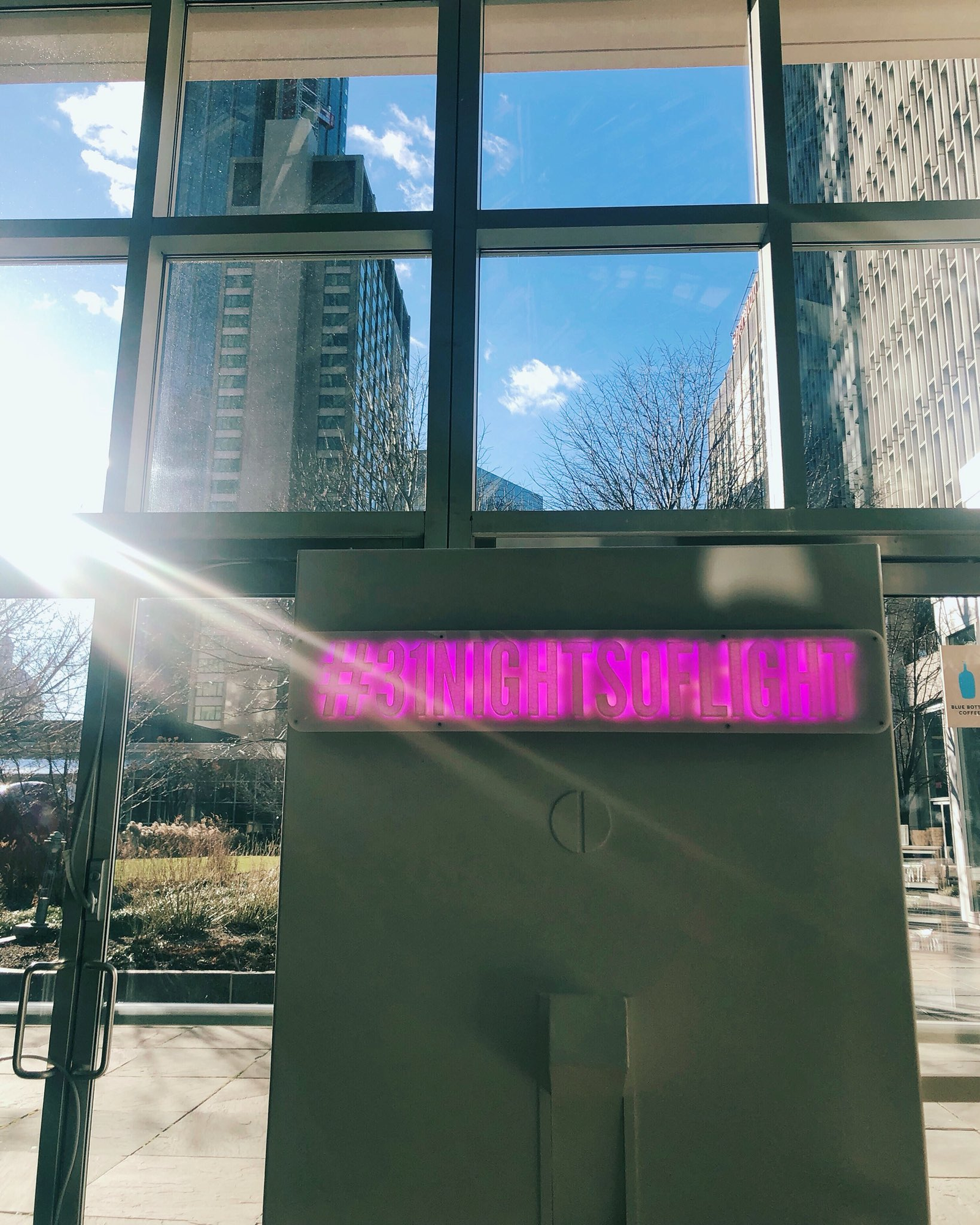
In late October of 2018, I began the CAD for such a project. Telapush had just closed our largest deal to date. We were to contracted to build a massive illuminated sign that would map social media interactions to custom animations to be displayed in real time. The piece was to run, un-attended for the entire month of December in the Center Court of the Prudential Center mall, inside of Boston’s most distinctive skyscraper.
Erin and I had been pouring effort into Telapush for some time, and this installation was to be the largest tangible result from that effort. Serious people spending real money and expecting actual results. Boston was my new home and I felt that this project was my chance to make a good first impression to this new and intimidating place. This heightened importance, paired with the reverence for the challenge, coaxed out some good engineering; the project was a rousing success. More details about this installation can be found in my portfolio entry on the project.
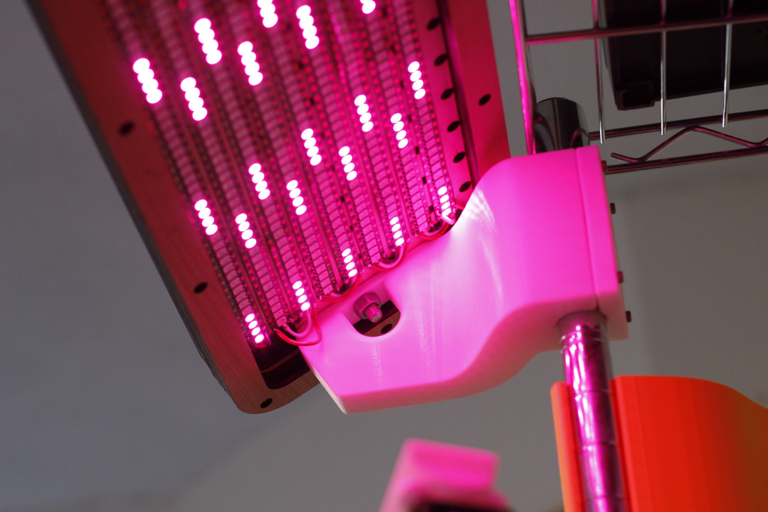
Luckily, one element of the installation that I was able to retain possession of after the installation concluded was the LED matrix. An overwhelming array of 1215 addressable LEDs, and a 100W power supply to drive them.
Still brimming with usefulness, and valuable as a totem commemorating the successful project, the light bar was filed into storage. Unfortunately, I lacked the bandwidth and inspiration to pick it back up. In the past few months however, on quiet nights, I could hear it calling out to me from the crawlspace, pleading to be reanimated. And after a few years of rest, this post describes how this favorite project is given a new lease on life to enhance my 3D printing workflow.
I work with addressable LEDs a lot. For all that they’re great for, they’re kind of hard to debug when you have a lot of them connected up at once. This is especially apparent when you have many small single modules in hard to reach spaces.
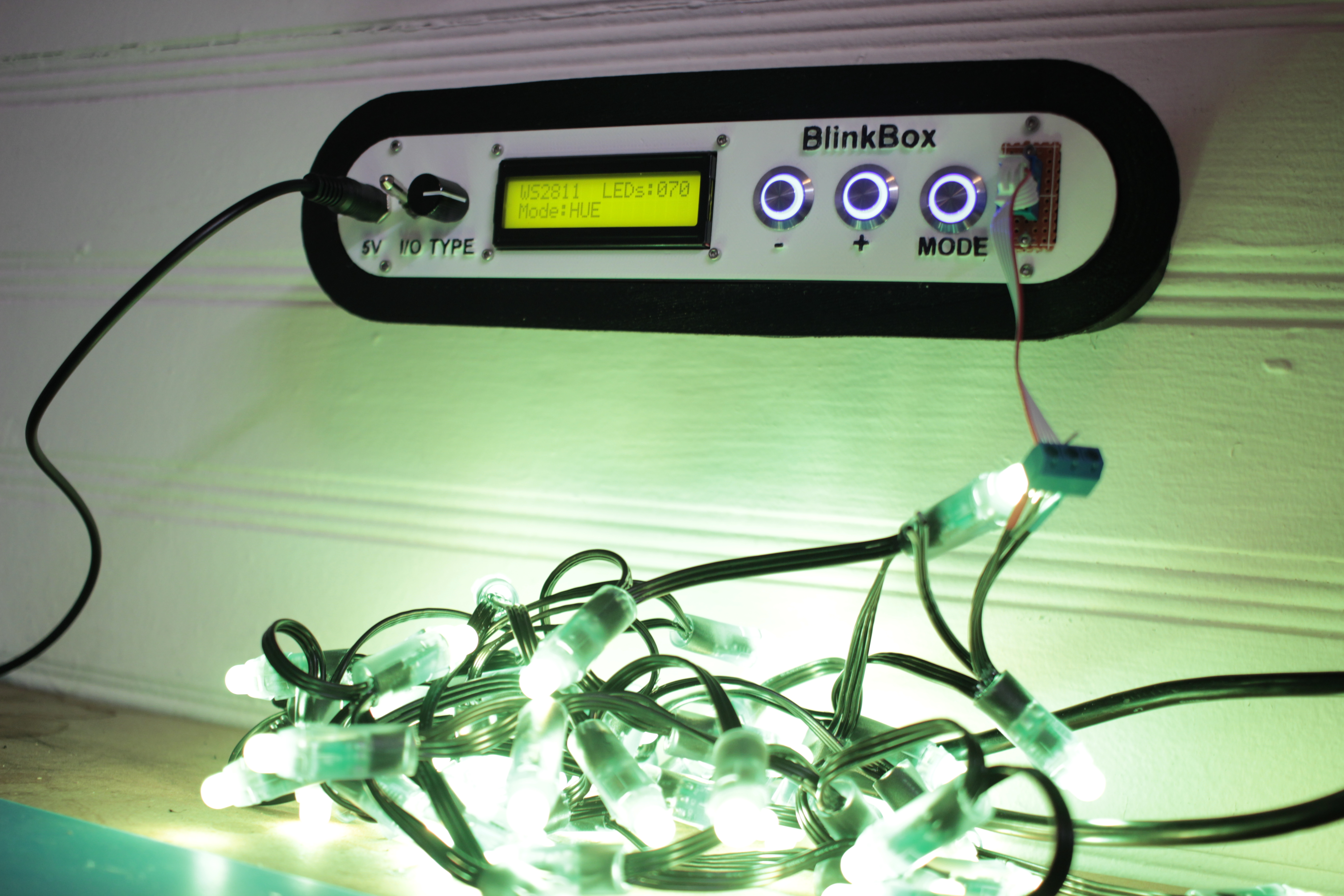
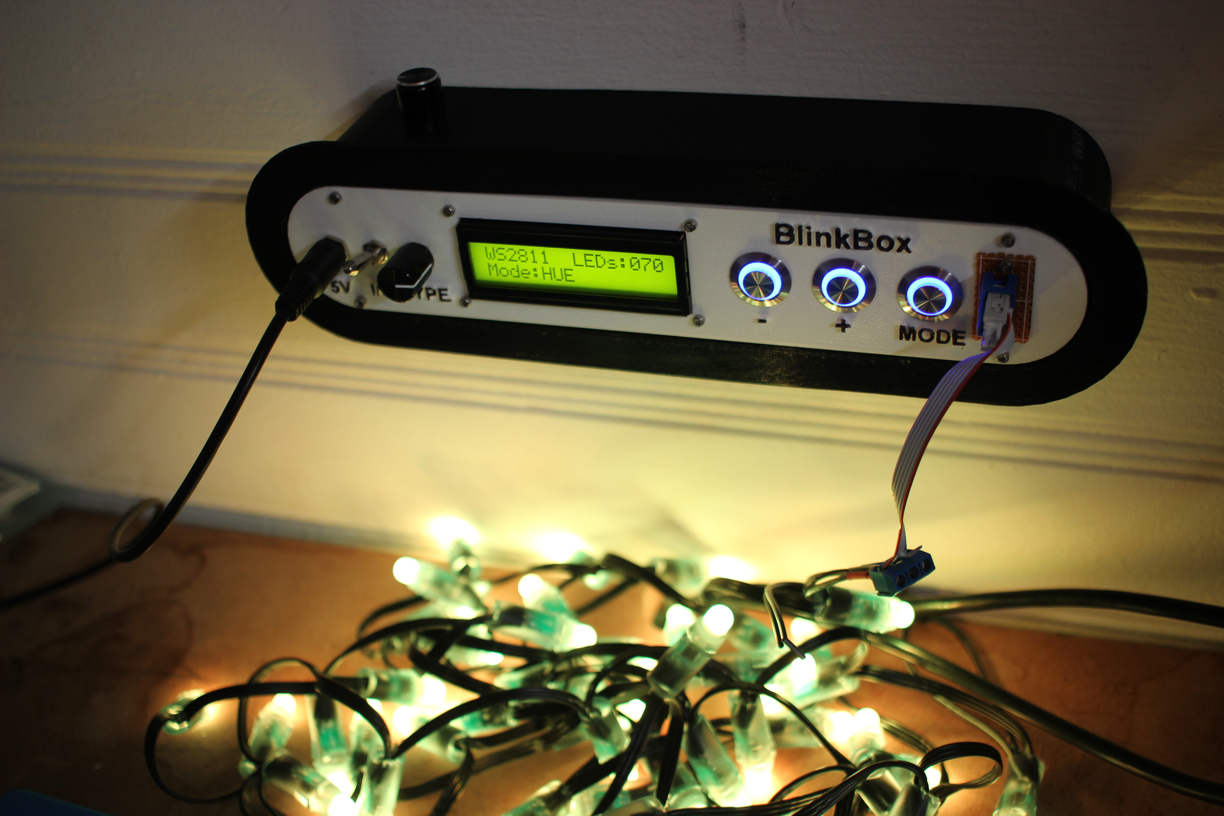
Here’s my solution:
This lets me set the color and number of LEDs in a strip, and then displays a color pattern. This way I can tell if an LED has become disconnected in a strip, or if a channel inside a particular has died.
Features
Select LED type with the type switch, 4 positions
Can test up to 400 LEDs at a time, if you can find a worthy power supply
3 Test modes
RGB – 1 second red, 1 second green, 1 second blue
HUE – Lock strip at HSV (x, 255, 255) and x loops from 0-255
WHTE – Set the strip to RGB(255, 255, 255)
Count and Mode are saved into eeprom, so you don’t have to keep resetting the strip if it powers off
Wall mount fittings
Design Explanation
All of the raw code solidworks, and KiCAD have been posted on my github. You can look at the 3D models on thingiverse as well.
Mechanical
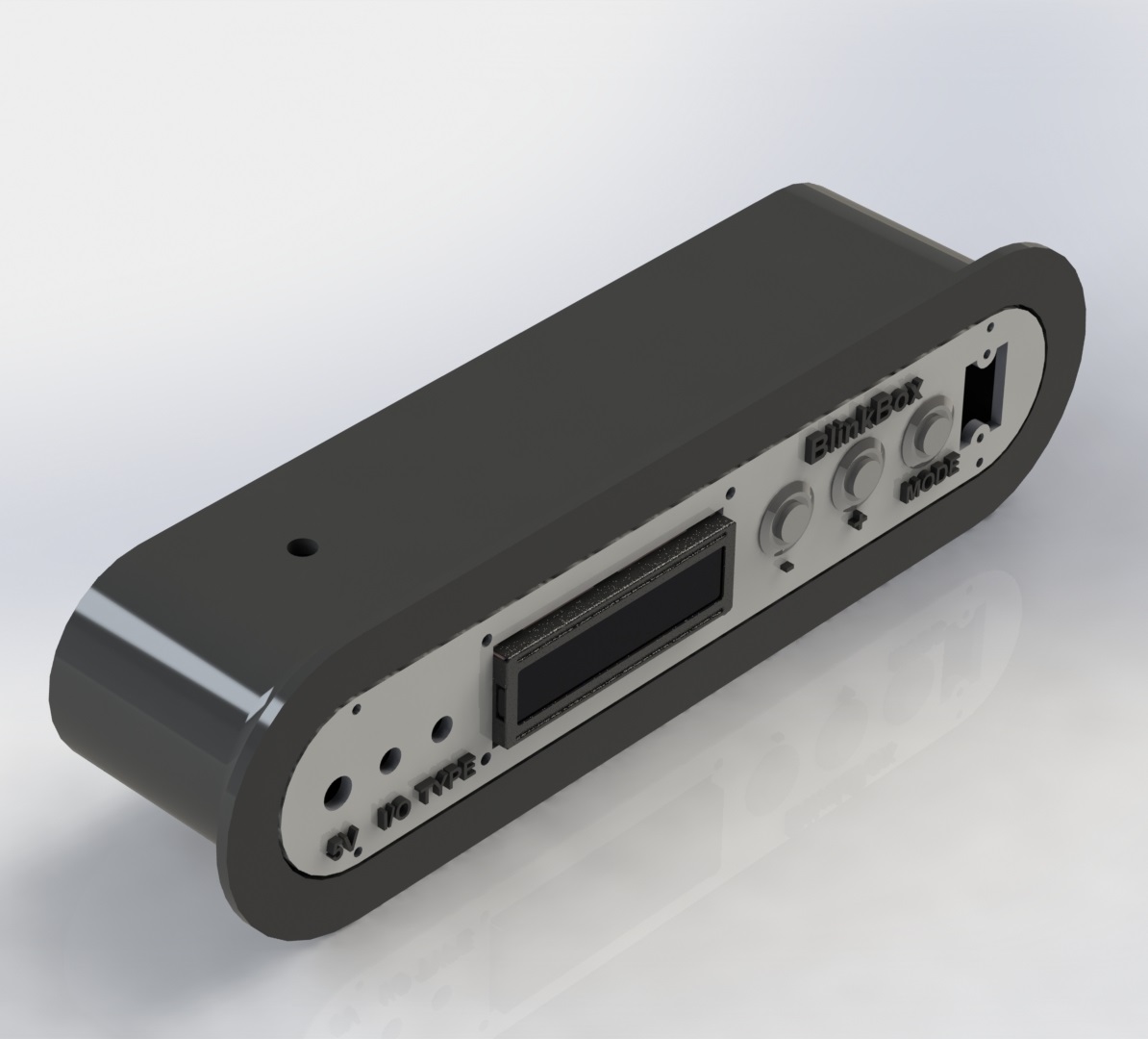
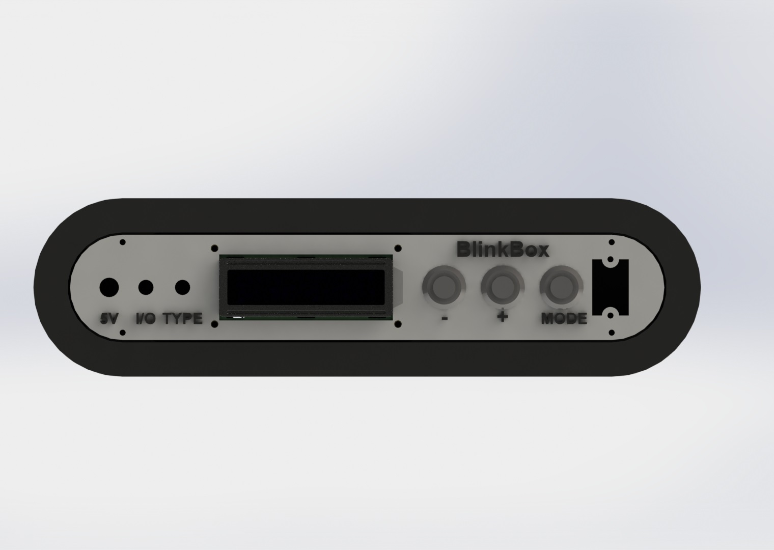
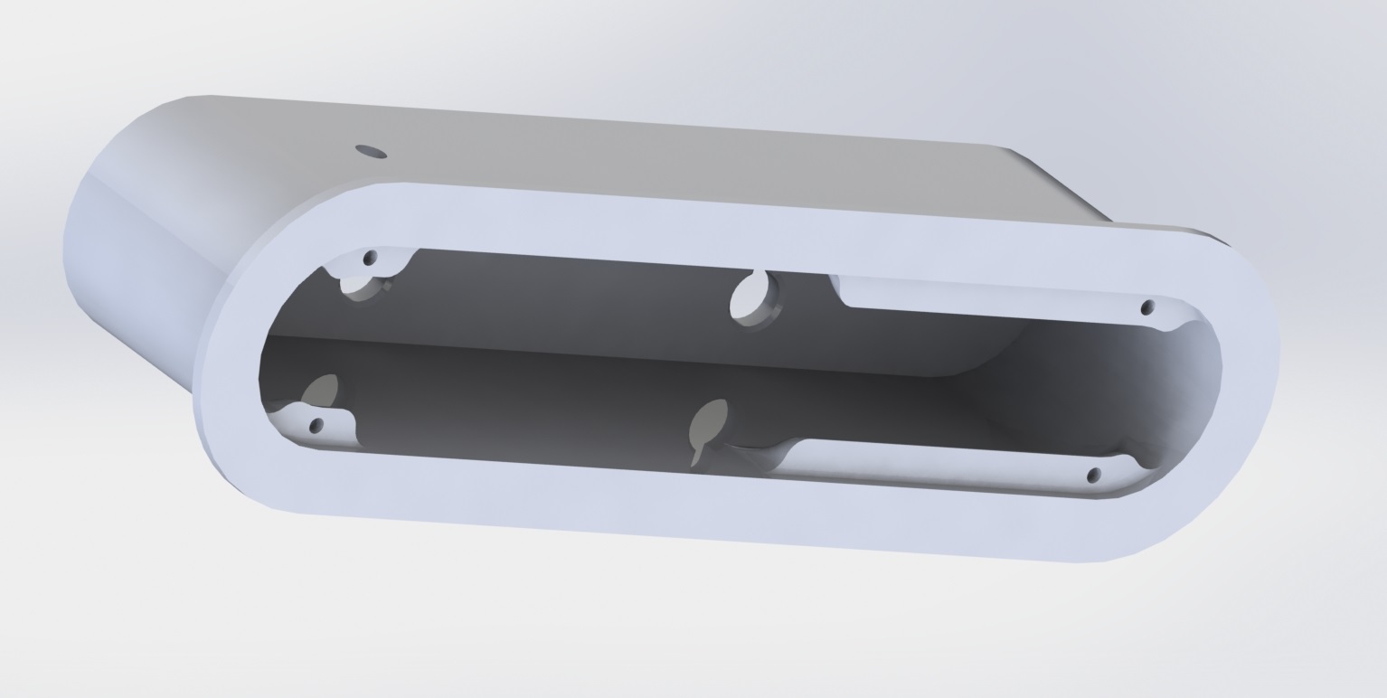
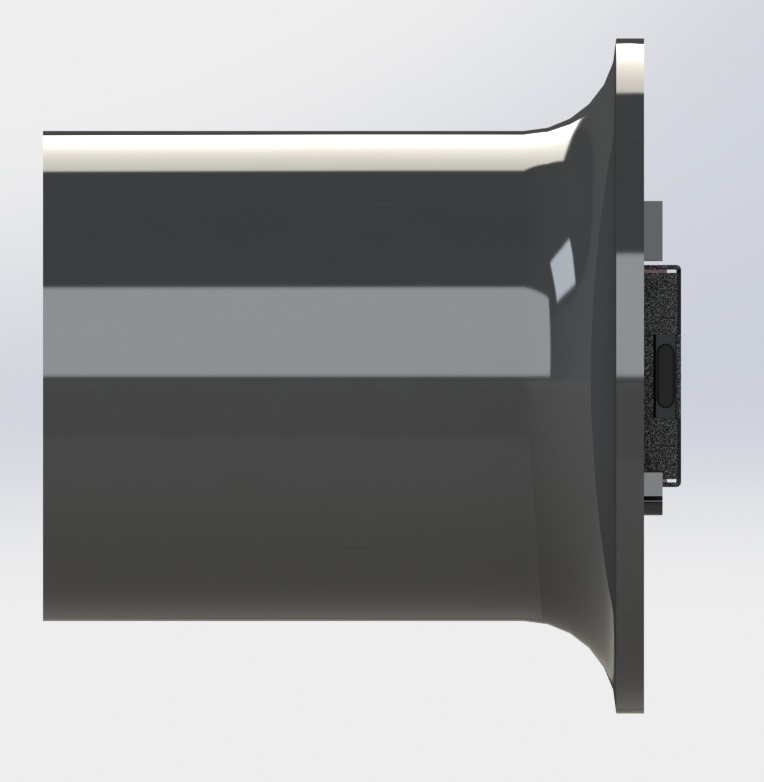
Here are a couple of quick renders of the assembly design:
The screw mount behind the pushbuttons is extended to be able to support the pressure without flexing: I added a ridge so you can grab onto something as you interact with the switches / buttons.
Electronics
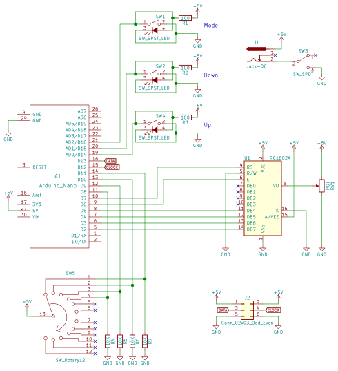
Here’s the circuit:
There really isn’t a lot going on here, the parts are probably the coolest part of the project. The 5V jack is a 6mm DC barrel jack, the pushbuttons are illuminated 16mm pushbuttons from adafruit, the on/off switch is a locking toggle switch, and the 4 position rotary switch can be found here.
I wired up the circuit on a spare piece of perfboard.
The LED driving part of the code is based on FastLED, a beautiful library for driving these types of addressable LEDs.
The rest of the code is mostly just a hardware UI problem, and isn’t all that interesting. LED count “ramps” as you hold the button down. The longer you hold the button, the faster the
Wrap up
That’s pretty much it! I’ve already gotten some use out of this tool and have found great satisfaction in taking the time to make it look nice as it will be a permanent addition to my lab.
I’ll post any updates I make to this project as edits to the top of this post.
Thanks for reading, and here are a few more photos:
First here’s a video of me demonstrating a few of the new features:
So compared to the original version of this project, the following changes are as follows:
Added function that takes image from incoming tweet, finds most common color in the image and writes it to the LEDs.
Added fading between colors instead of just jumping between them.
Added routine to respond to users when an error occurs in their tweet, like it’s missing a color or something is spelled wrong.
Re-Wrote most of code into an objects and methods on that object to get rid of global variables.
A few notes on the new features:
The operation of the image ingestion feature is pretty simple. All you have to do is tweet an image at @heyWPI just like you would with text. It finds the most common color in the image and then writes it the the LEDs. Here’s an example:
It works pretty well. If you look at the code, you’ll see that I tried to make it as modular as I could so I can possibly improve the color detection algorithm moving forward without making major changes in the code. This required the system to have some kind of memory to keep track of the current values written to the LEDs. Originally, I was using global variables to solve this problem but it wasn’t all that clean so I made it all more object oriented.
As for the fading You can sort of see it in the video, but the fading between colors looks really nice, especially from and to opposite complex colors like purple to orange.
A big problem I had with different people using the project was that sometimes people would use an invalid color. I implemented a default message to send if a received tweet didn’t have a color in the text or didn’t have an image in the body.
You should be ready to rock and roll on the software side, now let’s look at the hardware schematic.
I’ve tried to make this as simple as possible, but it probably isn’t the best way to drive these LEDs, moving forward I’d like to drive these strips with a constant current.
Using the python library, tweepy, getting the twitter interaction to work was actually very simple. The downside is that I can only retrieve mention data every 60 seconds due to Twitter’s API rate limiting.
The circuit is very simple, the RGB led strip I have is common anode, so I used N-Channel mosfets attached to pins 18 (Red), 23 (Green) and 24 (Blue). For the camera, I’m using a spare raspberry pi camera module I have.
For the names of the colors you can write to the lights, I went with the 140 X-11 colors. I figured it was a good spectrum of colors.
I’d love to expand the scale of the project, if you’re a student at wpi and would like on of these in your window, please email me at the addressed listed in the about section of my website.
PWM with a Raspberry Pi is tricky. There is an official meathod of doing this, but I’ve found that when driving multiple channels (like 3 for an RGB LED) it doesn’t work to well and is noticeably shaky when transitioning to new PWM cycles.
Looking for alternatives, I found pi-blaster. From their github:
This project enables PWM on the GPIO pins you request of a Raspberry Pi. The technique used is extremely efficient: does not use the CPU and gives very stable pulses.