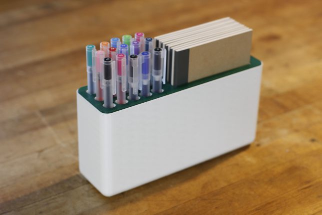
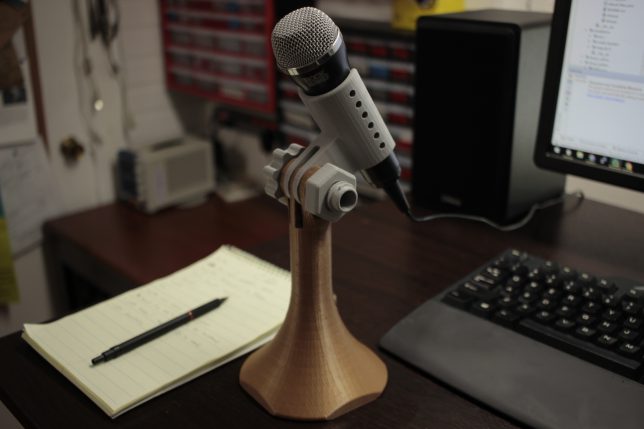
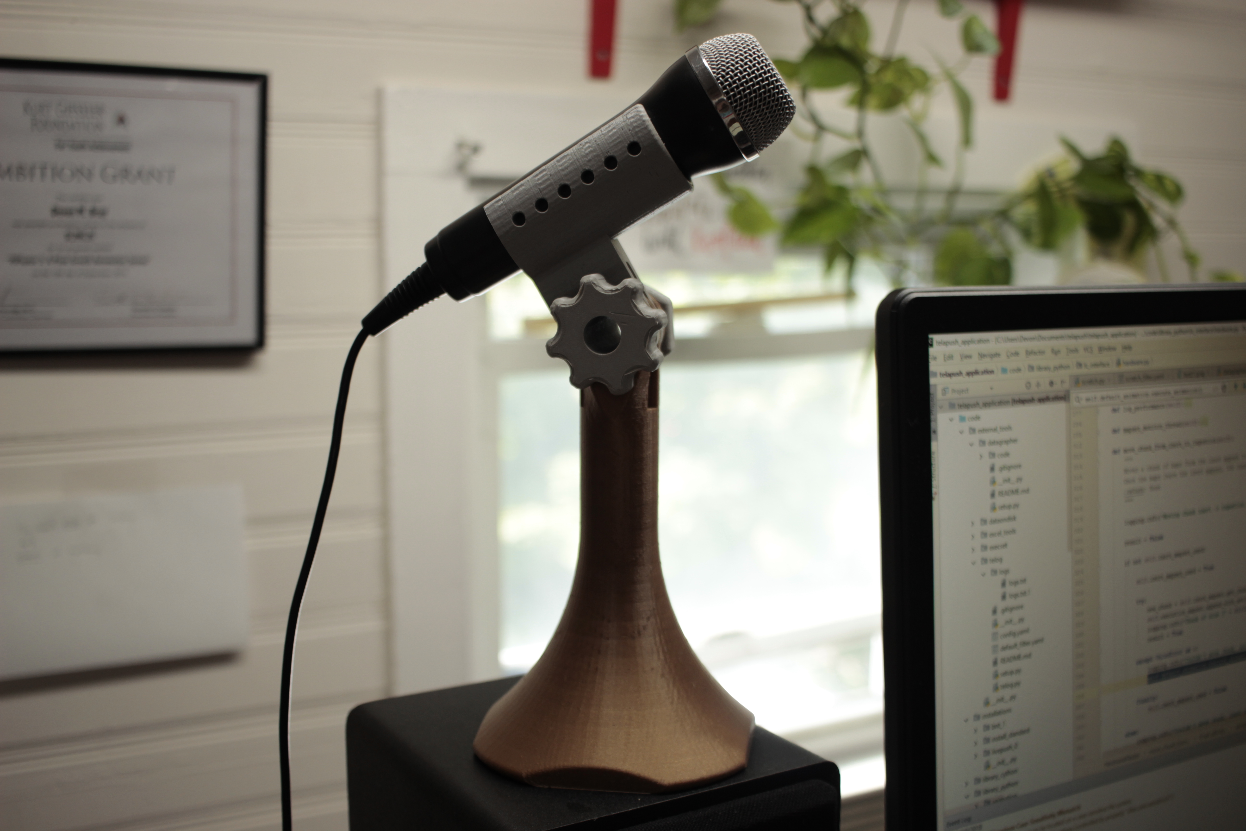
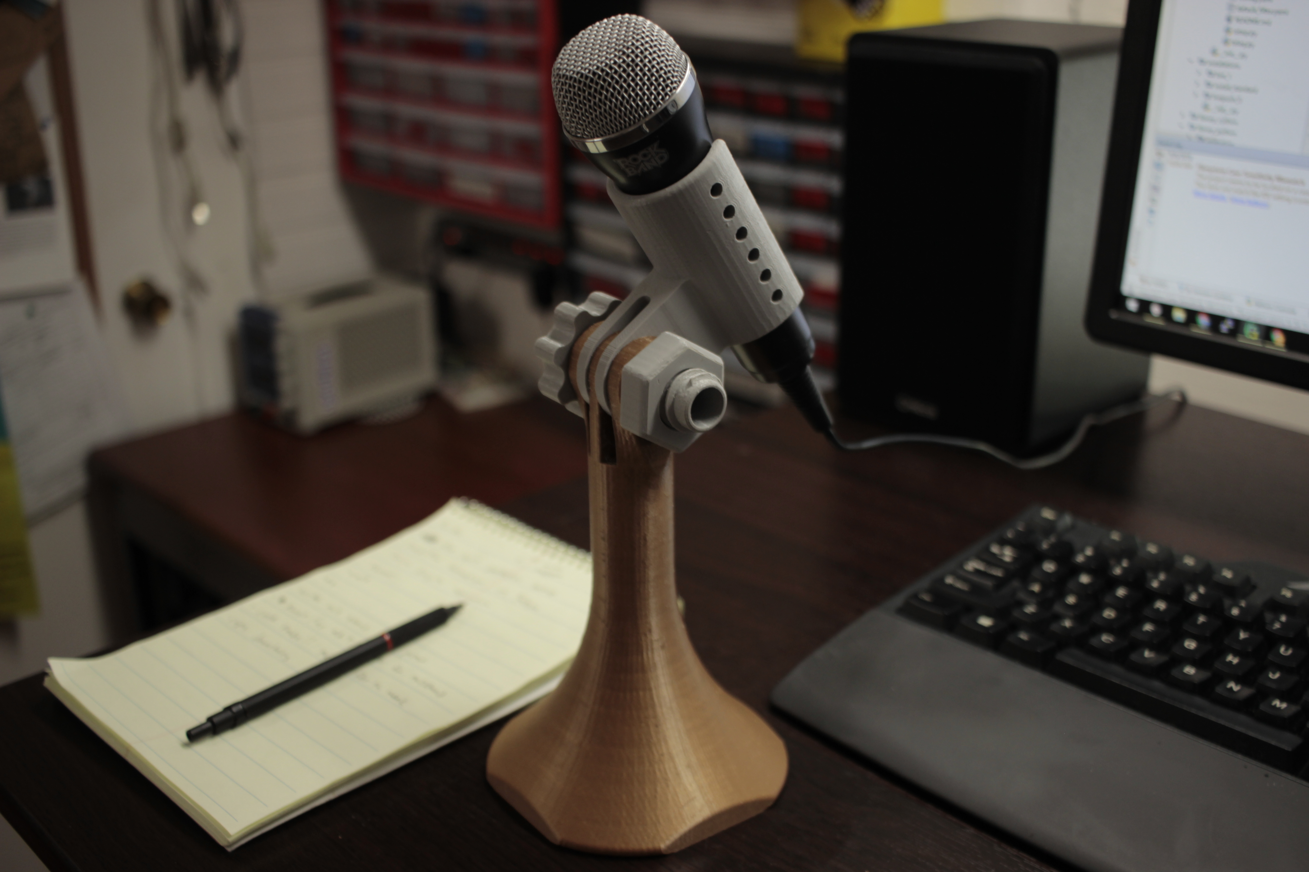
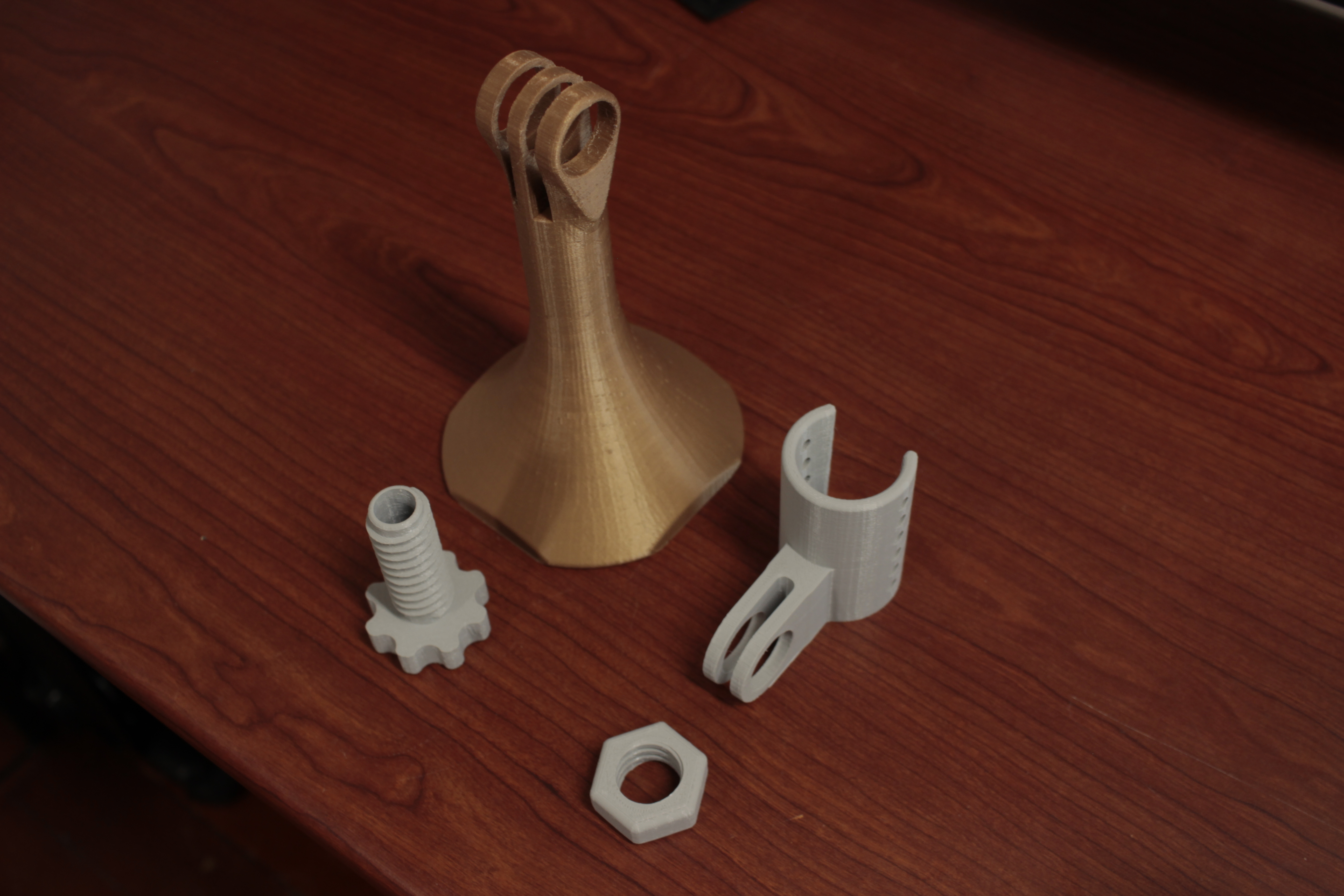
There have been afewposts on this blog about the functional benefits of using printed parts to join existing objects in a reliable and precise way. Most of the time my printed parts themselves look strange. The goals are usually printability and a clean assembly of printed and non-printed. As an attempt to buck this trend, I recently designed and manufactured a desktop organizer that showcases the medium’s ability to bond objects and also look great.
Looking for a wall mounted version of the HMD mount? Check out this remix on thingiverse (thanks Sean)!
Here’s a video going over the design:
The printed parts can all be found on thingiverse here. Please let me know if you use any of these! I’d love to talk about potential improvements that could be made.
I work with addressable LEDs a lot. For all that they’re great for, they’re kind of hard to debug when you have a lot of them connected up at once. This is especially apparent when you have many small single modules in hard to reach spaces.
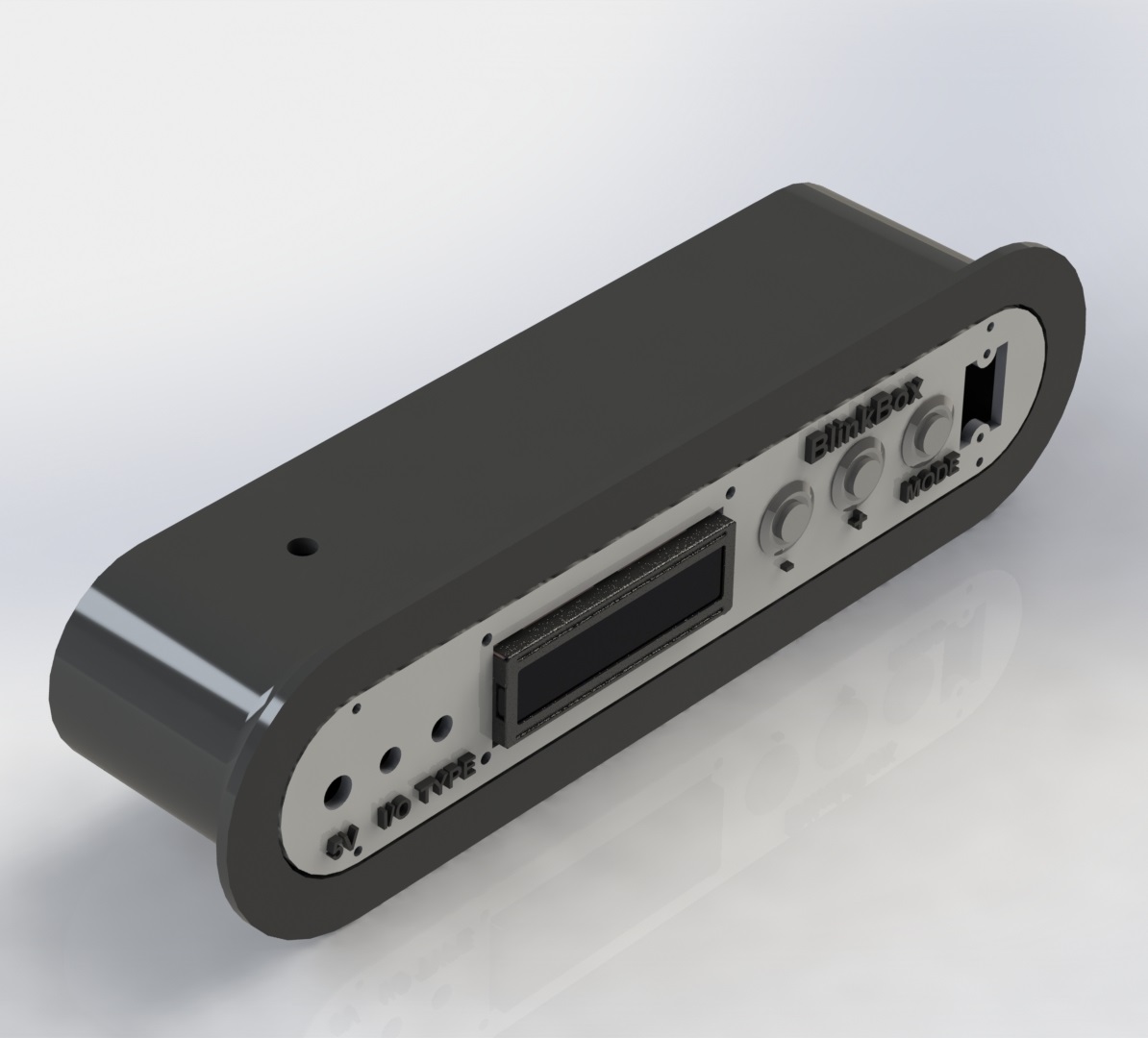
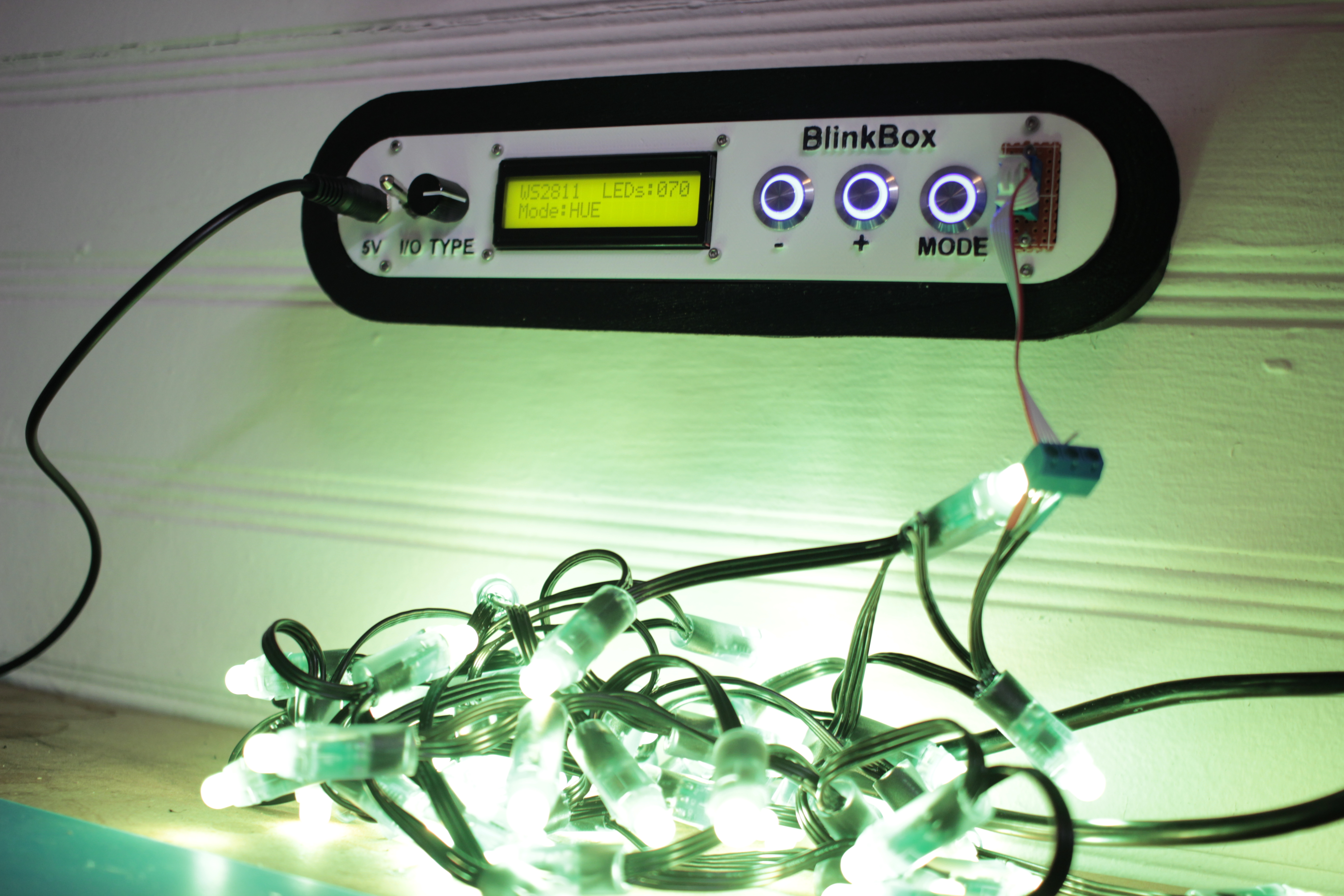
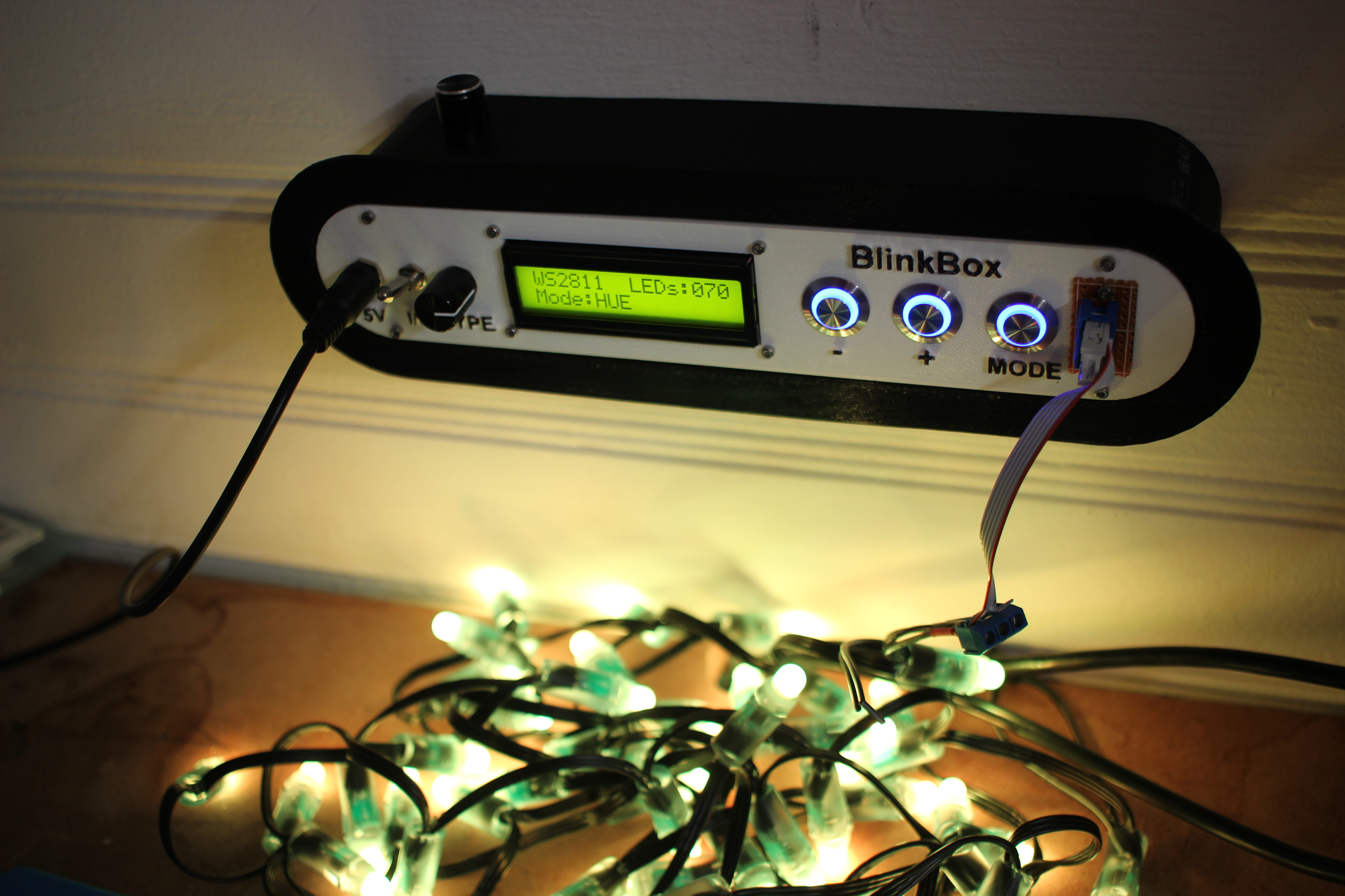
Here’s my solution:
This lets me set the color and number of LEDs in a strip, and then displays a color pattern. This way I can tell if an LED has become disconnected in a strip, or if a channel inside a particular has died.
Features
Select LED type with the type switch, 4 positions
Can test up to 400 LEDs at a time, if you can find a worthy power supply
3 Test modes
RGB – 1 second red, 1 second green, 1 second blue
HUE – Lock strip at HSV (x, 255, 255) and x loops from 0-255
WHTE – Set the strip to RGB(255, 255, 255)
Count and Mode are saved into eeprom, so you don’t have to keep resetting the strip if it powers off
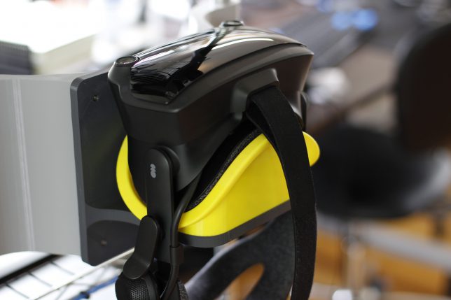
Wall mount fittings
Design Explanation
All of the raw code solidworks, and KiCAD have been posted on my github. You can look at the 3D models on thingiverse as well.
Mechanical
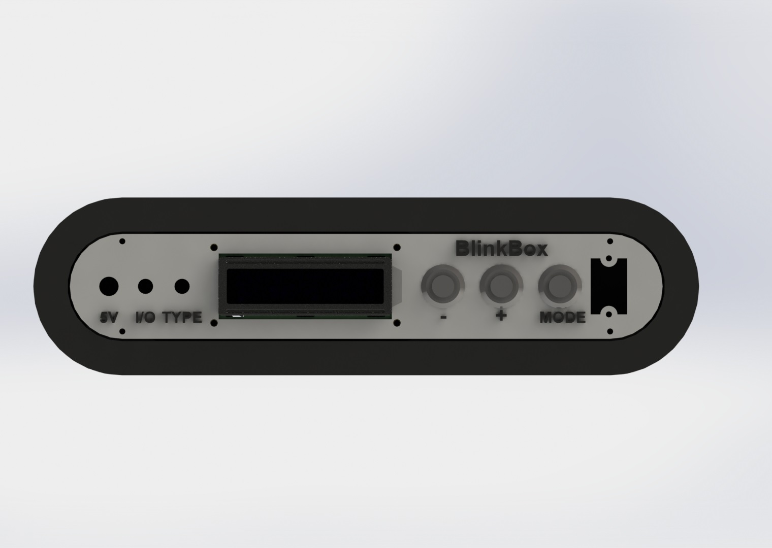
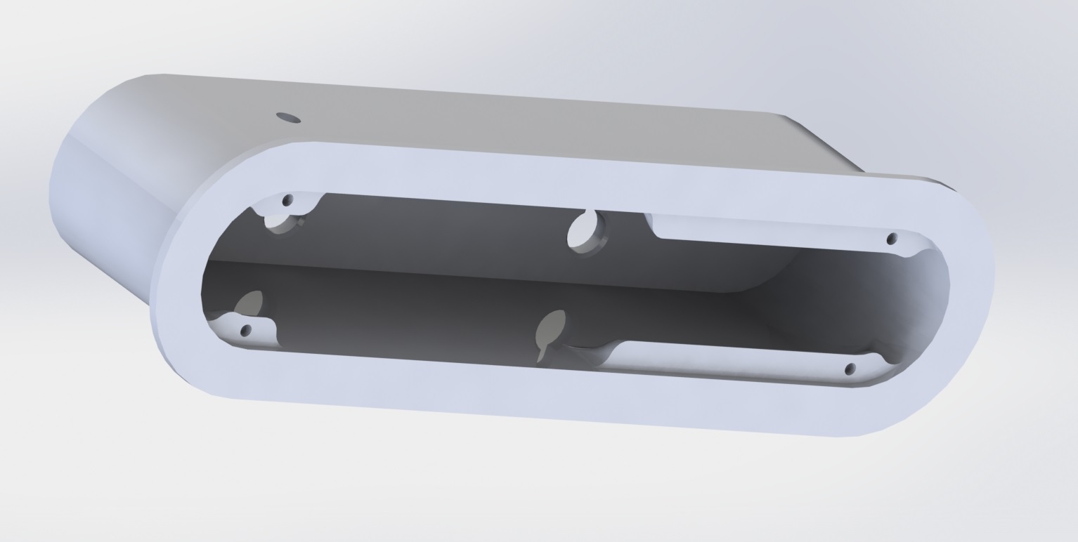
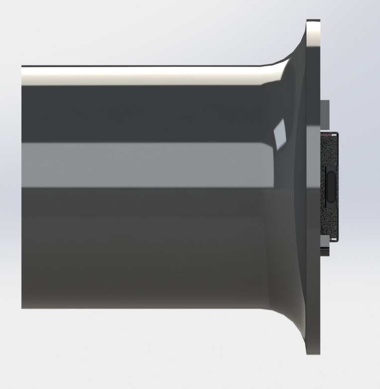
Here are a couple of quick renders of the assembly design:
The screw mount behind the pushbuttons is extended to be able to support the pressure without flexing: I added a ridge so you can grab onto something as you interact with the switches / buttons.
Electronics
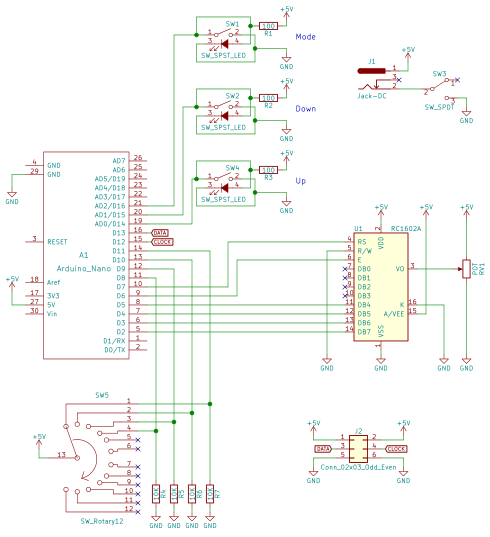
Here’s the circuit:
There really isn’t a lot going on here, the parts are probably the coolest part of the project. The 5V jack is a 6mm DC barrel jack, the pushbuttons are illuminated 16mm pushbuttons from adafruit, the on/off switch is a locking toggle switch, and the 4 position rotary switch can be found here.
I wired up the circuit on a spare piece of perfboard.
The LED driving part of the code is based on FastLED, a beautiful library for driving these types of addressable LEDs.
The rest of the code is mostly just a hardware UI problem, and isn’t all that interesting. LED count “ramps” as you hold the button down. The longer you hold the button, the faster the
Wrap up
That’s pretty much it! I’ve already gotten some use out of this tool and have found great satisfaction in taking the time to make it look nice as it will be a permanent addition to my lab.
I’ll post any updates I make to this project as edits to the top of this post.
Thanks for reading, and here are a few more photos:
It’s well known that nylon based 3D printer filaments need to be dried out before they’re used. What happens though when you have a 30+ hour print? The spool can take on a lot of moisture in that amount of time and compromise the print.
Many people have solved this problem by making filament dryboxes, somewhat airtight containers that contain a desiccant to dry out the air inside of the chamber.
I have to print several large parts from nylon for client, and I was having trouble in the last hours of the print due to the spool taking on water from the air. I decided to build one of these chambers but with a twist:
Mine is wall mounted! Space in my lab is a premium and the walls are free real estate.
The parts for this build is are available on my Thingiverse page. Oh and if you’re curious, I’m using a wall-outlet-rechargeable desiccant pack from Amazon which I got for $15.
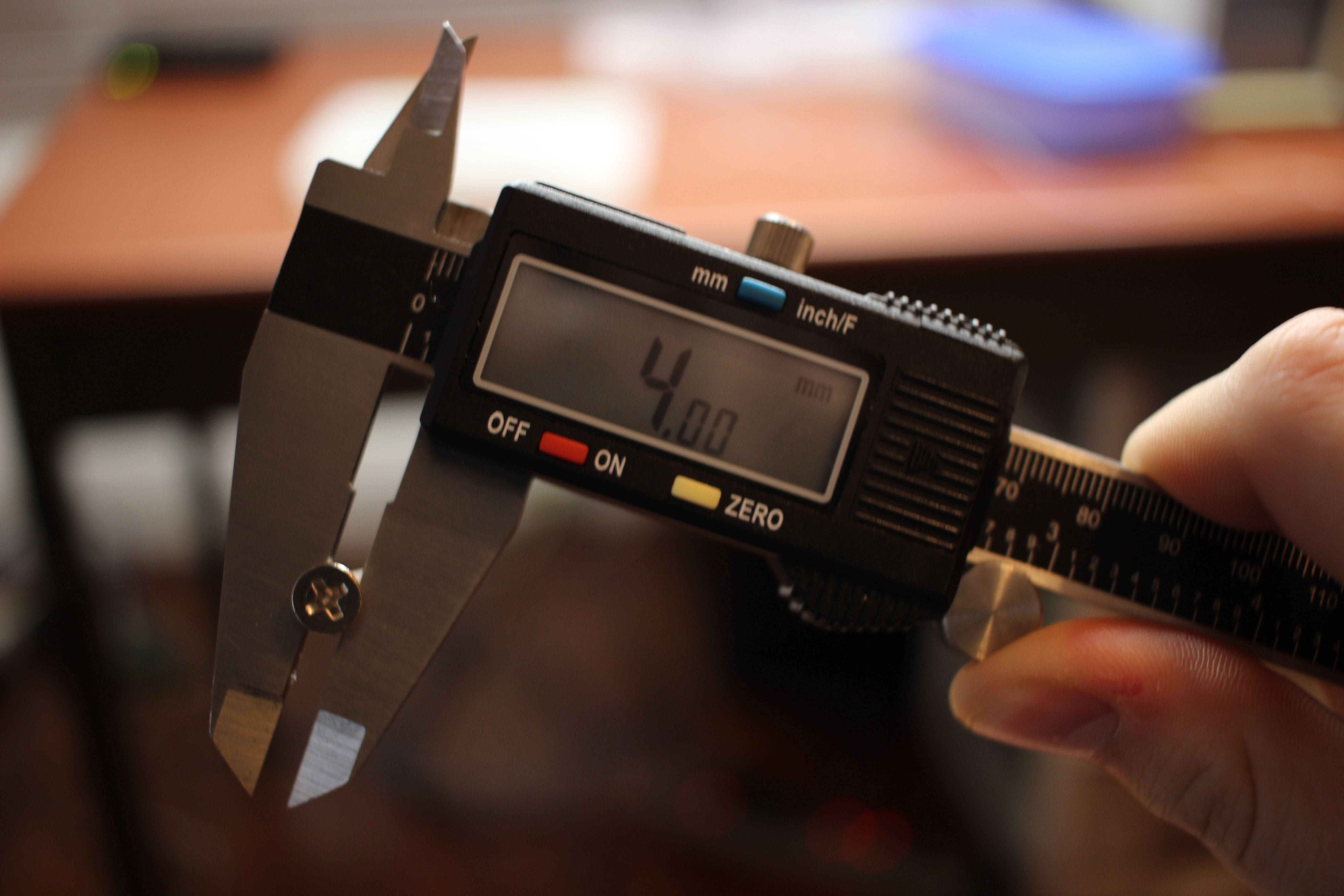
The bolts are M3x10mm, and the nuts are M3 nuts, both from McMaster Carr.
For a while I’ve been logging my favorite prints here but some of them are two small to warrant a post. So introducing: #goodprints! At first I’m going to shoot for monthly installments, but as I print more, I’ll post more.
This time we’ve got 3 prints in the above video. Here are the details:
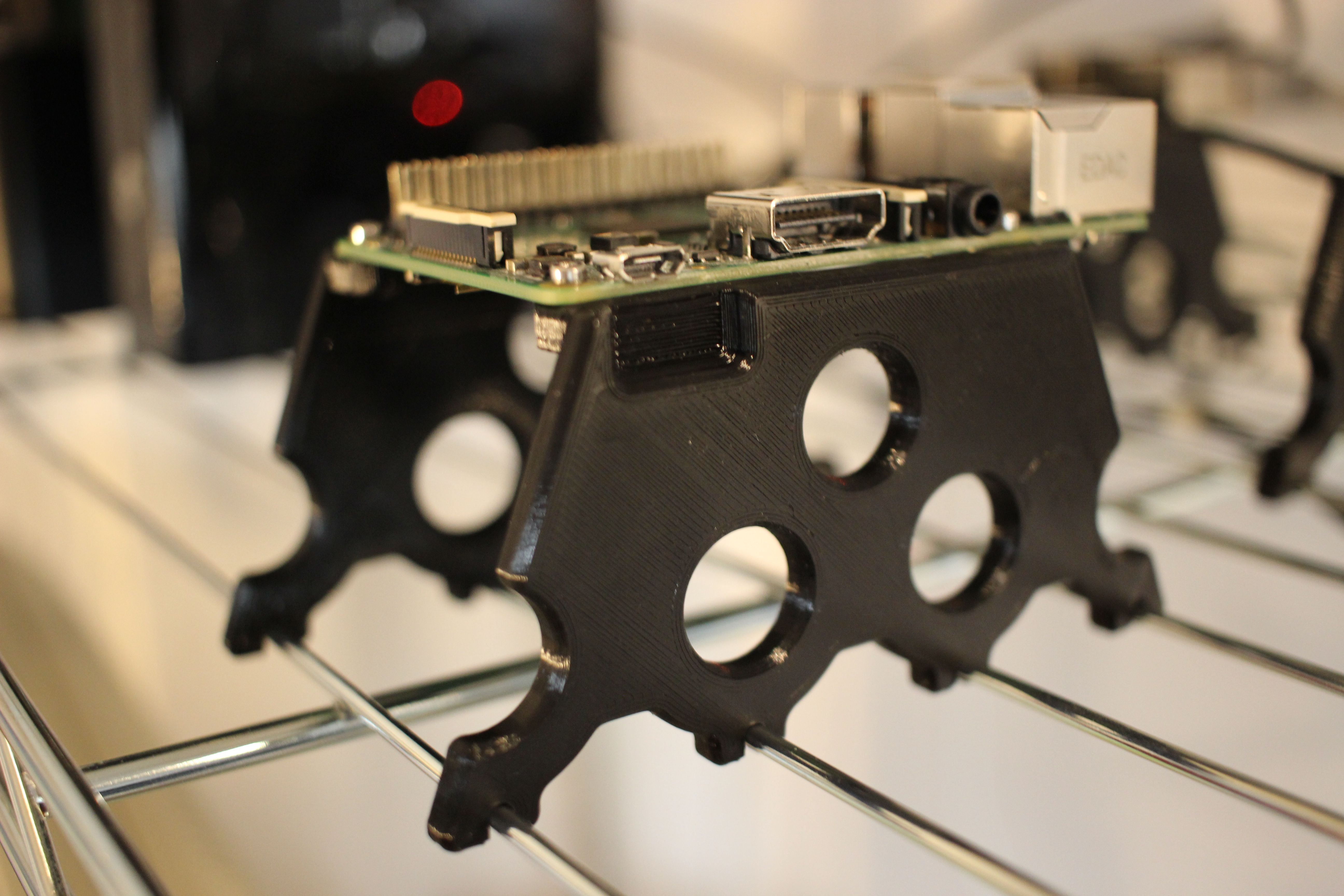
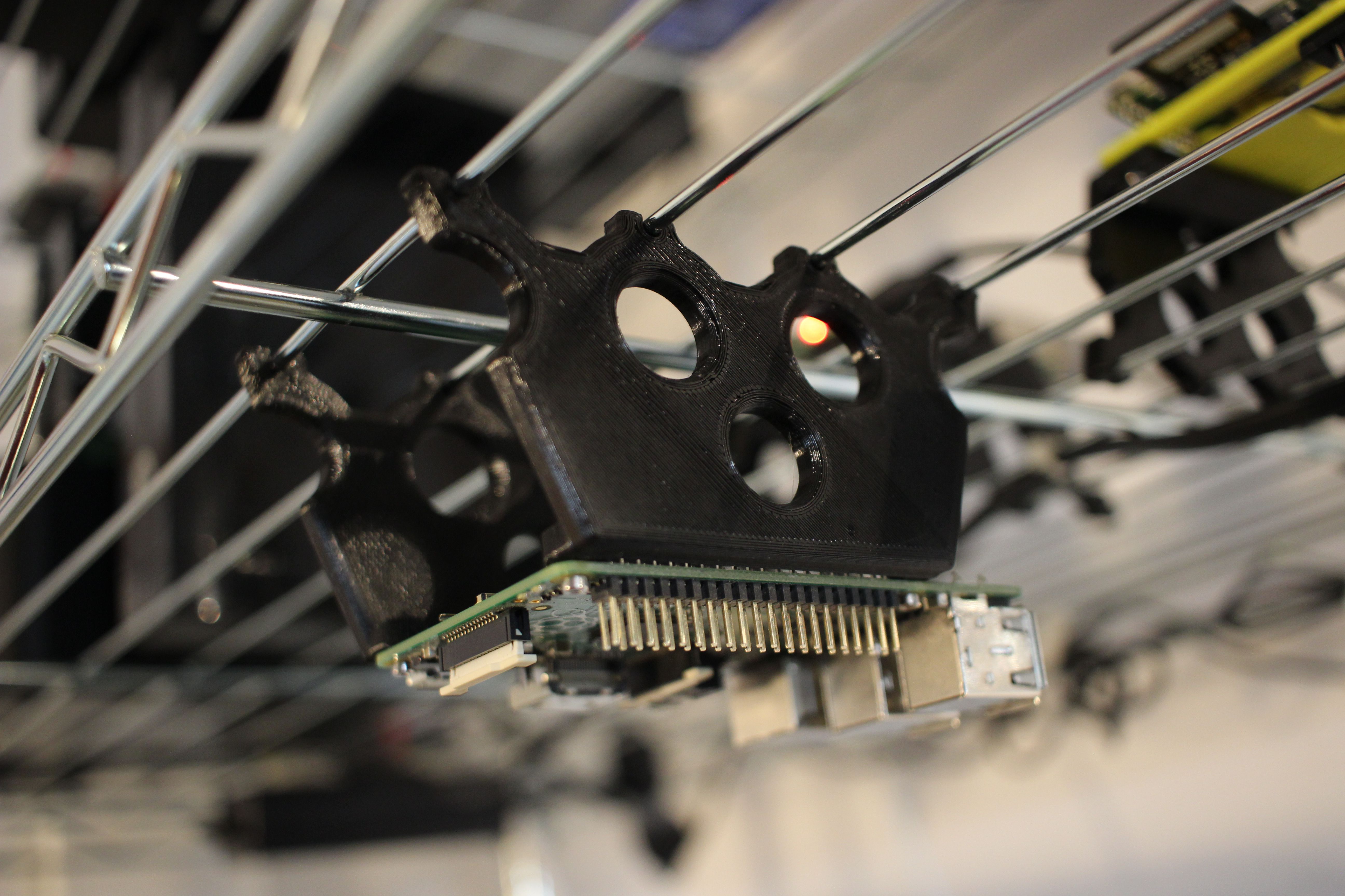
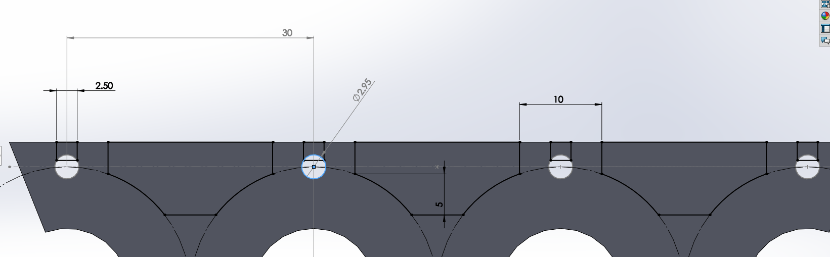
Raspberry Pi Wire Shelf Mount – Everyone knows that wire shelves are the best. Now you can securely mount a Raspberry Pi to one. Thingiverse Link
Here is the drawing for mating with the shelf:
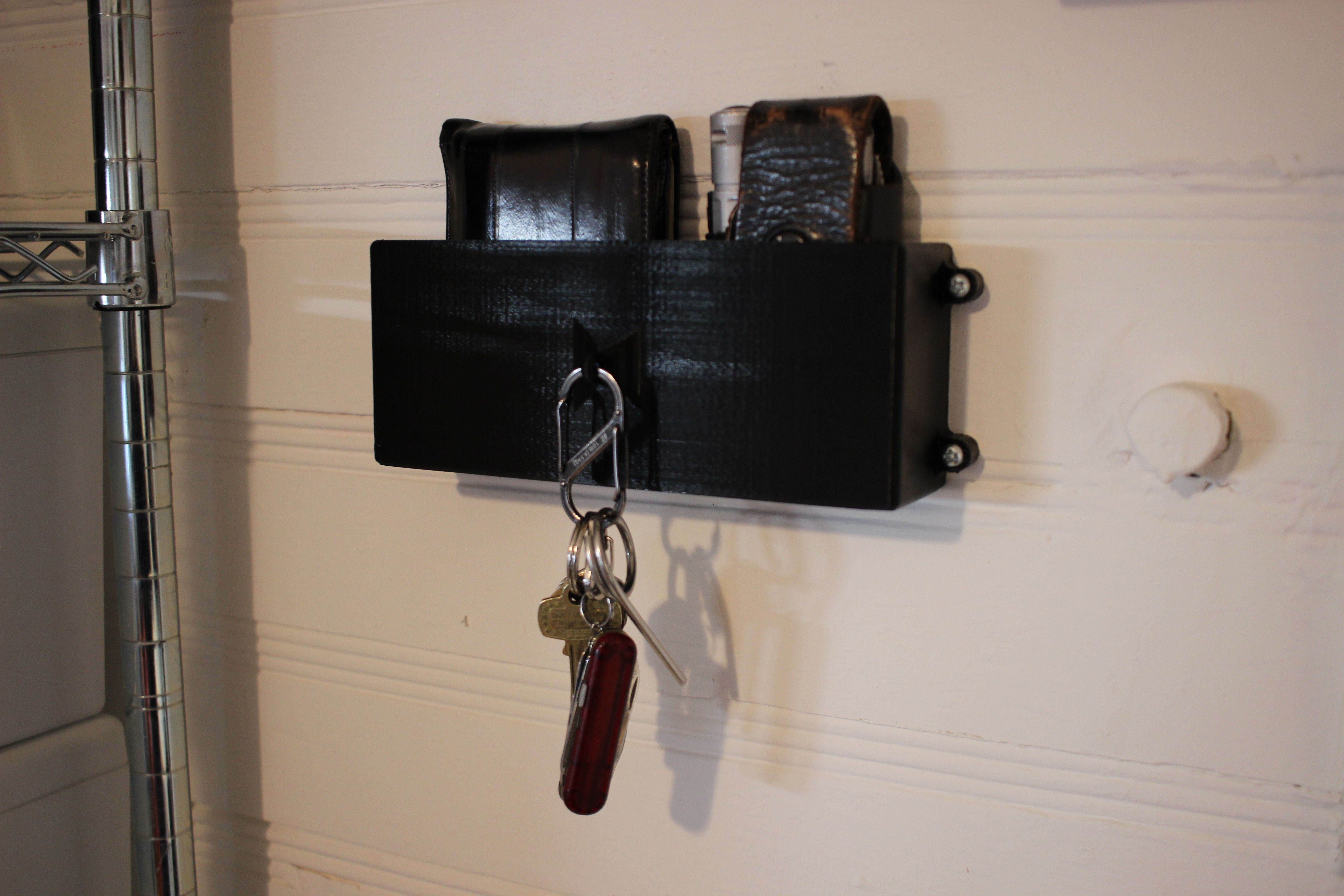
Wallet, Keys & Leatherman Wall Mount – I’m constantly loosing these things in my lab, now they’re not going anywhere. Thingiverse Link
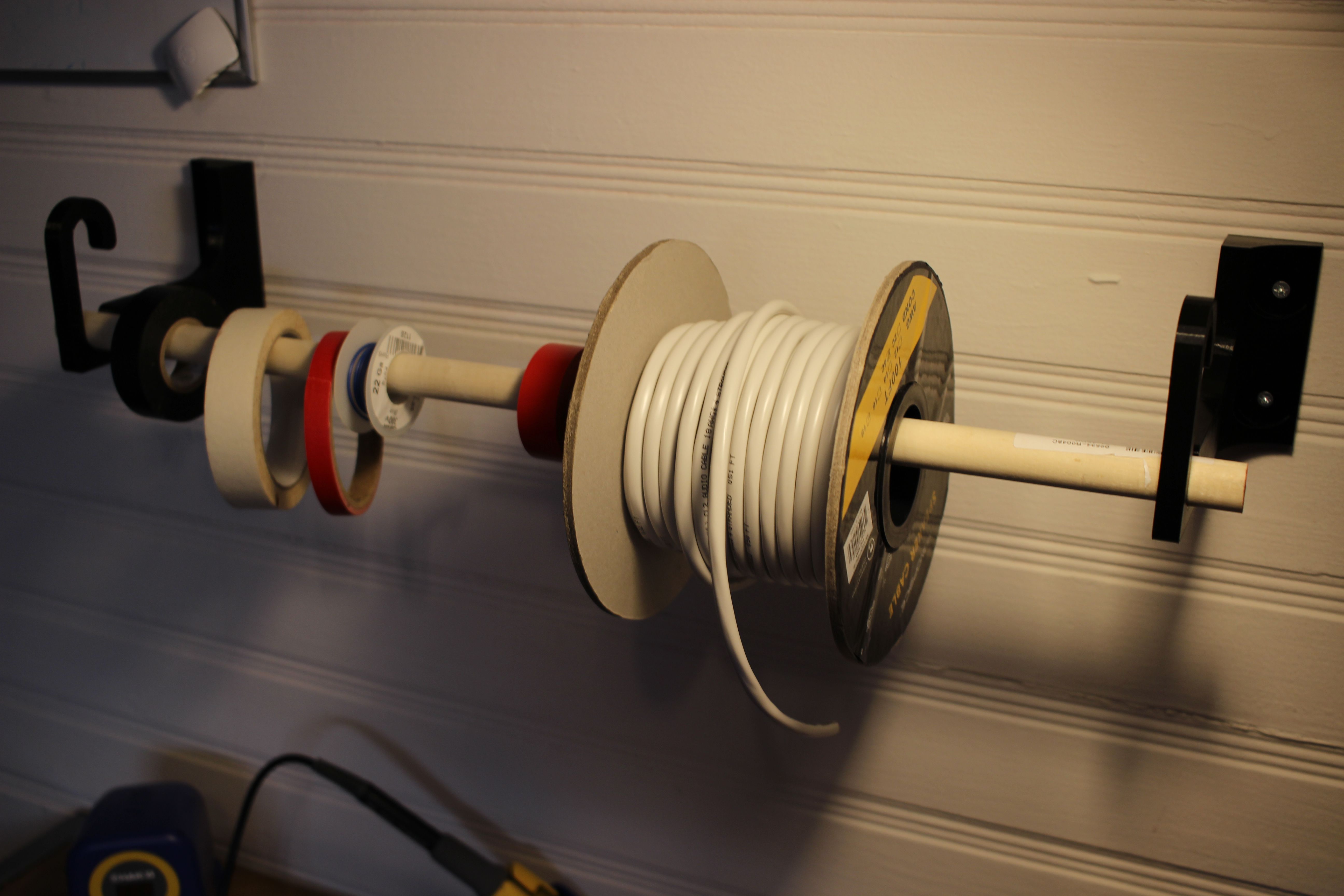
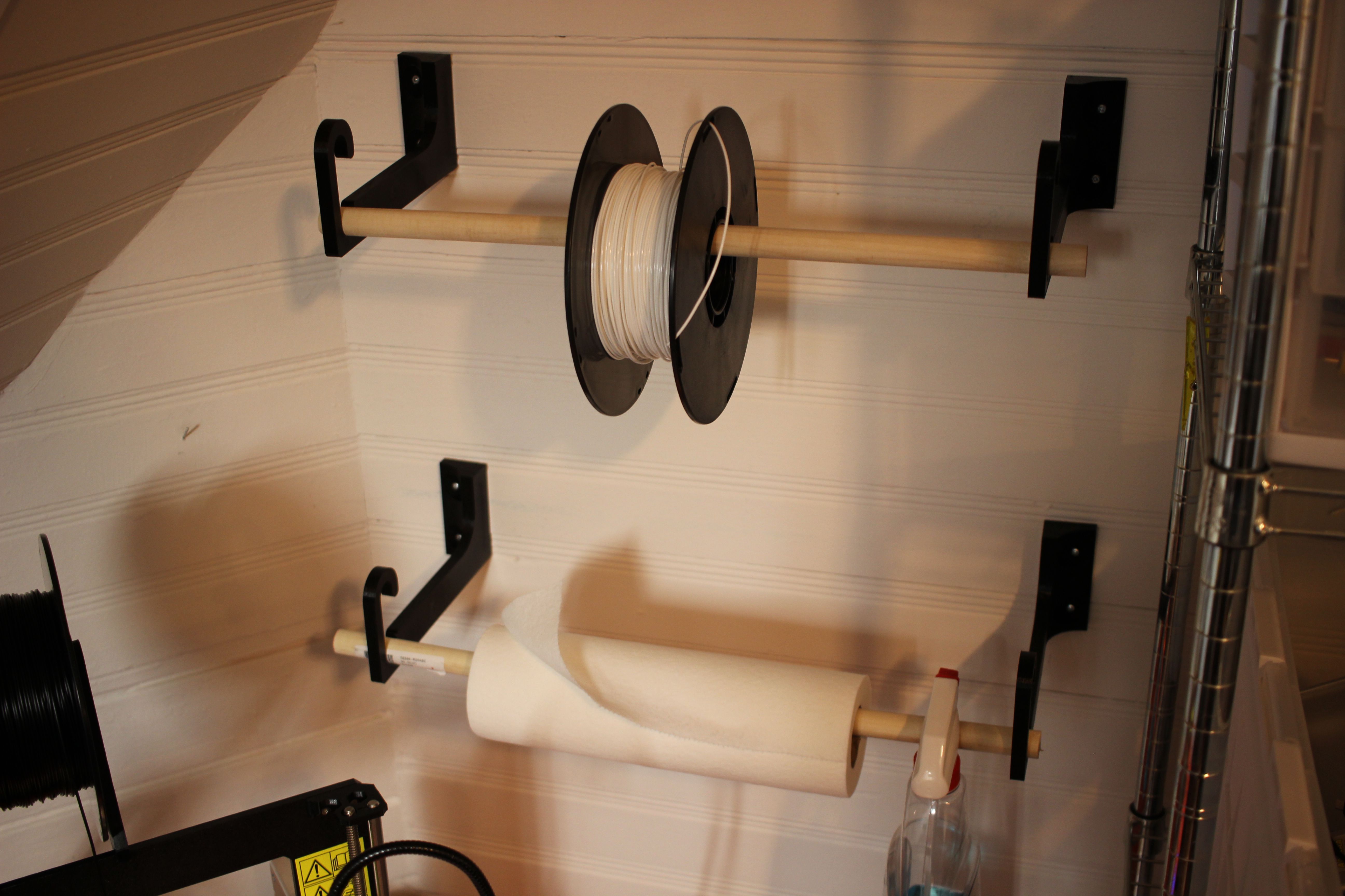
Wall Hook – This is for mounting stuff like filament spools, wire, and tape to the wall. It accepts 3/4 inchdowels. There are two version, one 85mm long and one 150mm long (designed to fit hatchbox 1kg filament spools). Thingiverse Link
This time we’re trying to work through a hardware bug!
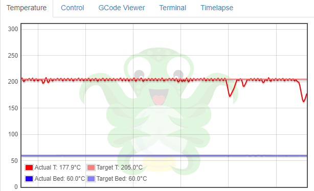
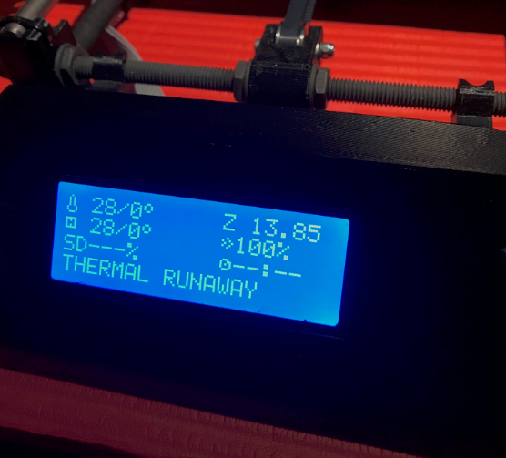
Without warning, my printer would stop it’s current print and display “THERMAL RUNAWAY” on the display screen:
This would happen once every couple of prints or so.
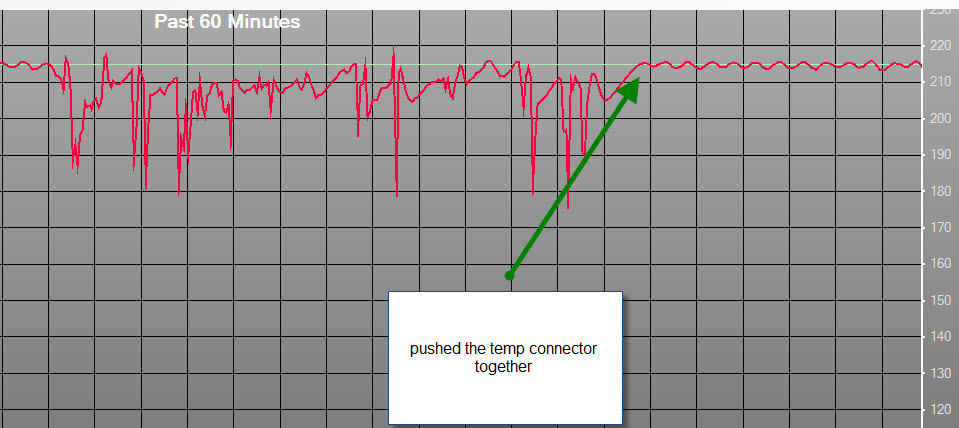
According Prusa’s Docs a common cause of this is problems with the thermistorconnection. They show a graph that has very erratic readings from the sensor:
This seemed like a good place to start so I re-seated the connector and used octoprint to generate my own graph:
No erratic readings, the temp would drop off and then start heating back up.
The problem ended up being the connection between the terminal lug and the wire on the heater in the hotend. To fix this, I cut off the crimp lug and stripped away some insulation. I put this into the screw terminal block. I’ve done a couple of prints and had no issues after making this modification.
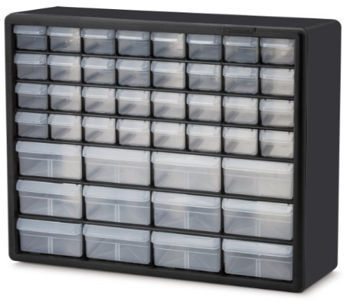
I use these Akro-Mils 10144 D sets of drawers to keep my various electronics components organized. They’re cheap, reasonable quality, but most importantly inexpensive.
Something that I find myself doing a lot is transferring individual drawers around. For example, I have a specific drawer that holds short jumper wires for breadboards. Sometimes I bring this drawer up to campus for working in the lab. Same goes for my misc-resistor drawer. It’s much easier to move the drawer rather than re-packing it.
The problem is that these are open drawers! They don’t have lids, so what I’ll do is put it in a ziplog bag and throw it into my backpack. This is a bad solution, I have a 3D printer, time to get CADing.
I wanted the drawer to be able to lock in place, so it wouldn’t slide out of the holder while in transit, here is a video of the locking mechanism in action:
As I iterated on this design, it became clear that I could get away with a pretty thin wall thickness, and that extending the slot cut made it much much easier to flex the locking mechanism, so the grab point on the outer surface became unnecessary.
Annoyingly, I couldn’t figure out a good solution to be able to use this part without having to use supports.
I recently purchased a Prusa i3 MK2 and it is glorious. The price was right, the assembly was straightforward and the print quality is probably better than I will ever need. After printing the requisite amount of dogs and other figurines, it’s time to start using this tool to improve my life.
I store a lot of my equipment on wire shelves. They’re cheap, easy to move around, and pretty strong. They can hold a lot of stuff, which means I keep a lot on them, and space, much like in the rest of my apartment, is limited. The server that is hosting this webpage lives on one of these shelves, and sometimes I have to manually work on it with a keyboard and monitor. It is a pain to have to dig out a keyboard, but it’s also not worth it to have a keyboard permanently on the shelf taking up space. That desire to maximize space is the motivation behind this project.


 This seemed like a good place to start so I re-seated the connector and used