Okay this post is going to be pretty media heavy, here’s a video of the overview of the system:
There are 4 main systems at work here, and like the video said I’ll be going over all of them.
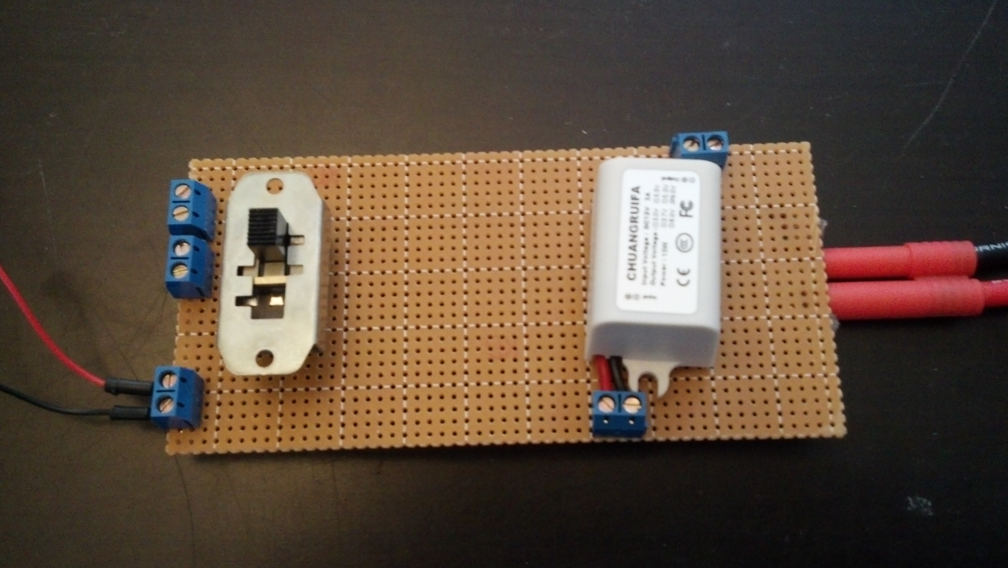
The first is the power system. At it’s core, it’s a Turnigy 5000mAh 3S 20C Lipo Battery Pack that is fed through two voltage converters. The first is 12v-9v@3A and the second is 12v-5v@3A. They are connected all via screw terminals in case they blow out. This all is fed through a large switch before it is fed into the controller and the motor driver, so it can all be cut off at a moments notice.
Here’s a video of me explaining that:
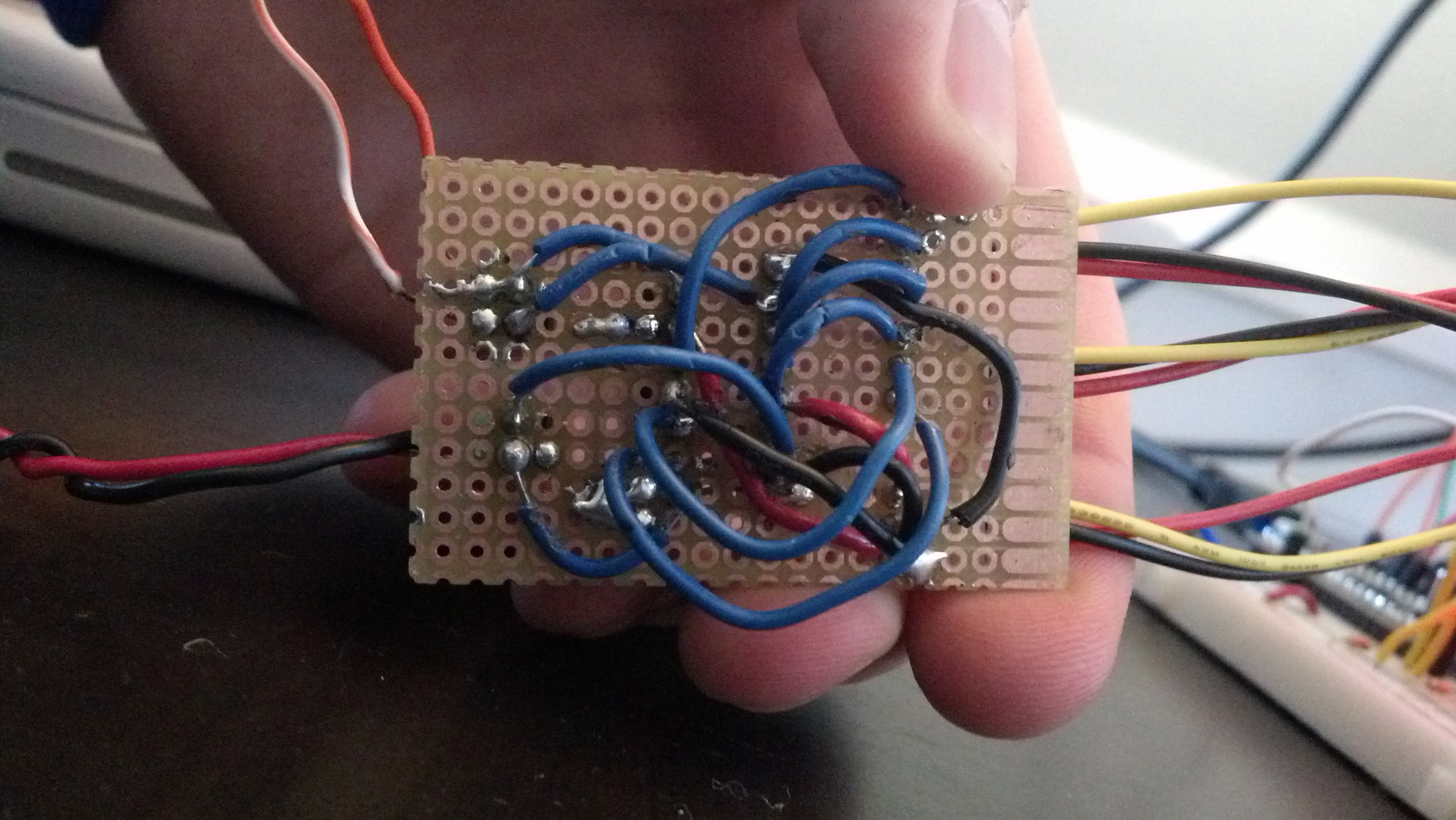
And here are some more detailed pictures:
This is the bottom, I’m still not great at going from breadboard to perfboard so bear with me.
And here’s the top without the 5v module installed, but it would be exactly the same as the 9v one that is:
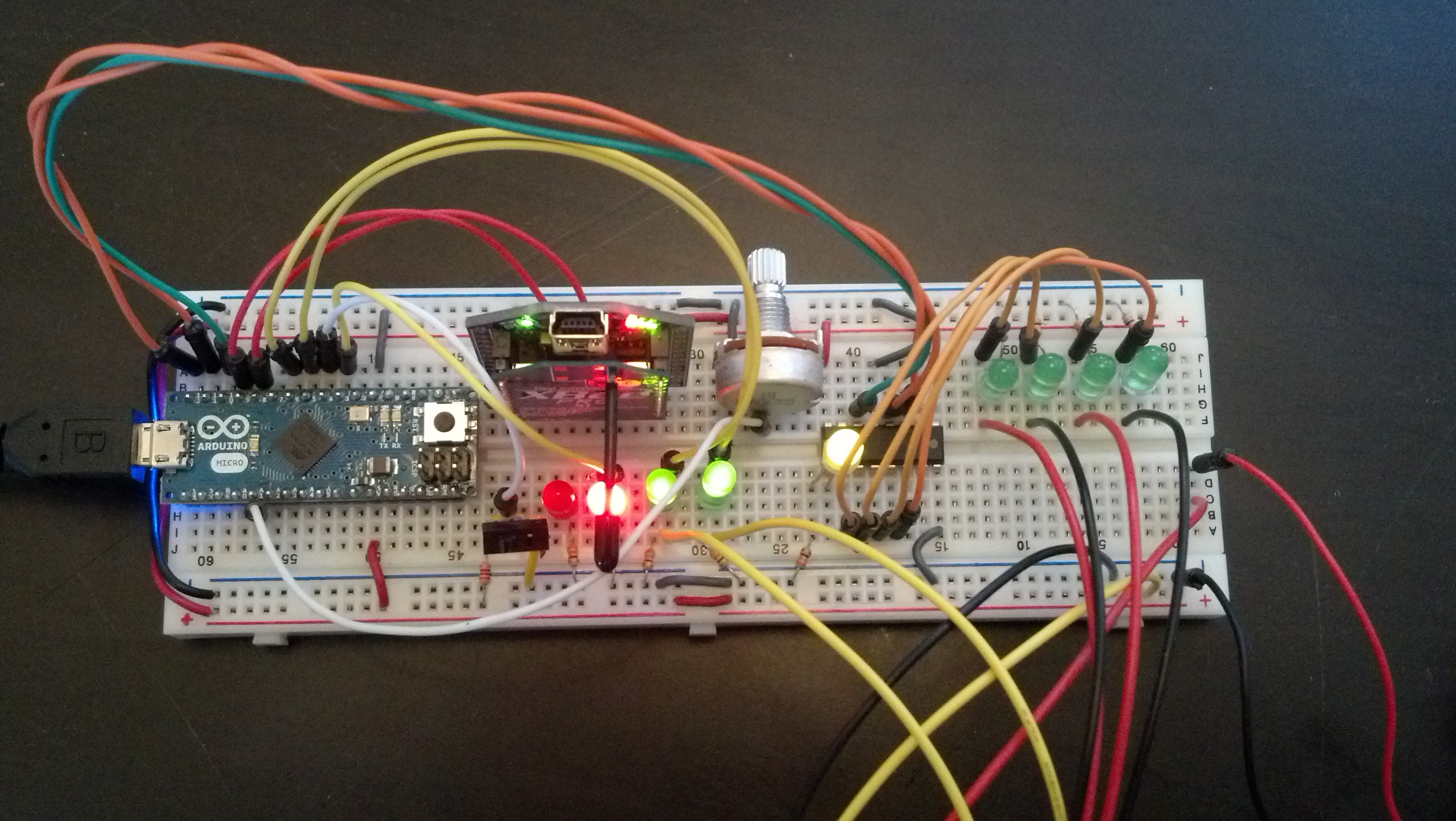
From there we go to the controller. It’s an Arduino Micro connected to a UartSBee V4 with a XBee Pro 60mW Wire Antenna – Series 1 (802.15.4) installed (the same goes for the controller). It also has a 74HC595 to free up pins which drive LED’s and the motor driver:
Here are some pictures:
Here’s the code:
//Serial Handshake declaration
#include <string.h> // we'll need this for subString
#define MAX_STRING_LEN 20 // like 3 lines above, change as needed.
const char EOPmarker = '.';  //This is the end of packet marker
char serialbuf[32]; //This gives the incoming serial some room. Change it if you want a longer incoming.

//SoftwareSerial declaration
#include <SoftwareSerial.h>
SoftwareSerial xbee_serial(8, 9);

//Shift Register Pins declaration
int SER_Pin = 10;   //pin 14 on the 75HC595
int RCLK_Pin = 11;  //pin 12 on the 75HC595
int SRCLK_Pin = 12; //pin 11 on the 75HC595
#define number_of_74hc595s 1 //How many of the shift registers - change this
#define numOfRegisterPins number_of_74hc595s * 8 //do not touch
boolean registers[numOfRegisterPins];

//Servo declarations
#include <Servo.h>
Servo left_servo;
Servo rght_servo;

//Misc Pin declaration

//inputs
int pot = 1;
int debug_switch1 = 4;

//outputs
int fade_LED = 3;
int x_LED = 5;
int y_LED = 6;
//int debug_switch1_LED = 12;

//Misc Integer declarations
int brightness = 0;    // how bright the LED is
int fadeAmount = 20;    // how many points to fade the LED by

int x_upperTrigger = 600;
int x_lowerTrigger = 400;
int y_upperTrigger = 600;
int y_lowerTrigger = 400;

void setup(){
  Serial.begin(9600);
  xbee_serial.begin(9600);

  pinMode(SER_Pin, OUTPUT);
  pinMode(RCLK_Pin, OUTPUT);
  pinMode(SRCLK_Pin, OUTPUT);
  pinMode(0, INPUT);
  clearRegisters();
  writeRegisters();

  pinMode(pot, INPUT);
  pinMode(debug_switch1, INPUT);

  pinMode(x_LED, OUTPUT);
  pinMode(y_LED, OUTPUT);
  pinMode(fade_LED, OUTPUT);

  xbee_serial.print("0,0,0."); // this is very important as it starts of the loop because it makes "xbee_serial.avalible() > 0.
}

void loop(){
  if (xbee_serial.available() > 0) {
    static int bufpos = 0;
    char inchar = xbee_serial.read();
      if (inchar != EOPmarker) {
        serialbuf[bufpos] = inchar;
        bufpos++;
      }
      else {
        serialbuf[bufpos] = 0; //restart the buff
        bufpos = 0; //restart the position of the buff

          handshake();
          debug_handshake();

          setRegisterPin(1, HIGH);
          writeRegisters();

    }
  }
}

void handshake(){
  //input, recived from controller
  // led1val,ledval2,fade_LEDvalue.

  //analogWrite(x_LED, map(atoi(subStr(serialbuf, "," , 1)),0,1023,0,255));
  //analogWrite(y_LED, map(atoi(subStr(serialbuf, "," , 2)),0,1023,0,255));
  analogWrite(fade_LED, atoi(subStr(serialbuf, "," , 3)));

  brightness = brightness + fadeAmount;
  // reverse the direction of the fading at the ends of the fade:
  if (brightness == 0 || brightness == 255) {
    fadeAmount = -fadeAmount ;
  }

  if (atoi(subStr(serialbuf, "," , 1)) > x_upperTrigger ){
    analogWrite(x_LED, map(atoi(subStr(serialbuf, "," , 1)),512,1023,0,255));
    setRegisterPin(2, HIGH);
    setRegisterPin(3, LOW);
    writeRegisters();
  }

  if (atoi(subStr(serialbuf, "," , 1)) < x_lowerTrigger ){
    analogWrite(x_LED, map(atoi(subStr(serialbuf, "," , 1)),512,0,0,255));
    setRegisterPin(2, LOW);
    setRegisterPin(3, HIGH);
    writeRegisters();
  }

  if (atoi(subStr(serialbuf, "," , 1)) > x_lowerTrigger && atoi(subStr(serialbuf, "," , 1)) < x_upperTrigger){
    setRegisterPin(2, LOW);
    setRegisterPin(3, LOW);
    writeRegisters();
  }

  if (atoi(subStr(serialbuf, "," , 2)) > y_upperTrigger ){
    analogWrite(y_LED, map(atoi(subStr(serialbuf, "," , 2)),512,1023,0,255));
    setRegisterPin(4, HIGH);
    setRegisterPin(5, LOW);
    writeRegisters();
  }

  if (atoi(subStr(serialbuf, "," , 2)) < y_lowerTrigger ){
    analogWrite(y_LED, map(atoi(subStr(serialbuf, "," , 2)),512,0,0,255));
    setRegisterPin(4, LOW);
    setRegisterPin(5, HIGH);
    writeRegisters();
  }

  if (atoi(subStr(serialbuf, "," , 2)) > y_lowerTrigger && atoi(subStr(serialbuf, "," , 2)) < y_upperTrigger){
    setRegisterPin(4, LOW);
    setRegisterPin(5, LOW);
    writeRegisters();
  }

  //output, sent to controller
  //ledpot1,fade_LEDval.
  xbee_serial.print(analogRead(pot));
  xbee_serial.print(",");
  xbee_serial.print(brightness); //This second byte is for the purpose of the program, it is not being used.
  xbee_serial.print("."); //EOP marker
  delay(10);
}

void debug_handshake(){
  //input, recived from controller
  Serial.print("VEHICLE DEBUG: ");
  Serial.print("INPUTS|");
  Serial.print(" x_LED: ");
  Serial.print(map(atoi(subStr(serialbuf, "," , 1)),0,1023,0,255));
  Serial.print(" y_LED: ");
  Serial.print(map(atoi(subStr(serialbuf, "," , 2)),0,1023,0,255));
  Serial.print(" in fade_LED: ");
  Serial.print(atoi(subStr(serialbuf, "," , 3)));

  //output, sent to controller
  Serial.print(" OUTPUTS|");
  Serial.print(" Pot 1: ");
  Serial.print(analogRead(pot));
  Serial.print(" out fade_LED: ");
  Serial.print(brightness);
  Serial.println("");
}

char* subStr (char* input_string, char *separator, int segment_number) {
 char *act, *sub, *ptr;
 static char copy[MAX_STRING_LEN];
 int i;

 strcpy(copy, input_string);

for (i = 1, act = copy; i <= segment_number; i++, act = NULL) {

 sub = strtok_r(act, separator, &ptr);
 if (sub == NULL) break;
 }
 return sub;
}

void clearRegisters(){
  for(int i = numOfRegisterPins - 1; i >=  0; i--){
     registers[i] = LOW;
  }
}

void writeRegisters(){
  digitalWrite(RCLK_Pin, LOW);
  for(int i = numOfRegisterPins - 1; i >=  0; i--){
    digitalWrite(SRCLK_Pin, LOW);
    int val = registers[i];
    digitalWrite(SER_Pin, val);
    digitalWrite(SRCLK_Pin, HIGH);
  }
  digitalWrite(RCLK_Pin, HIGH);
}

//set an individual pin HIGH or LOW
void setRegisterPin(int index, int value){
  registers[index] = value;
}
Next is the motor driver. It’s built around the L298N. Here’s the video
Here are pictures:
It’s my first real use of a perfboard to make a project more permanent which is why it looks awful, but this is what it should look like:
Image generated by fritzing.
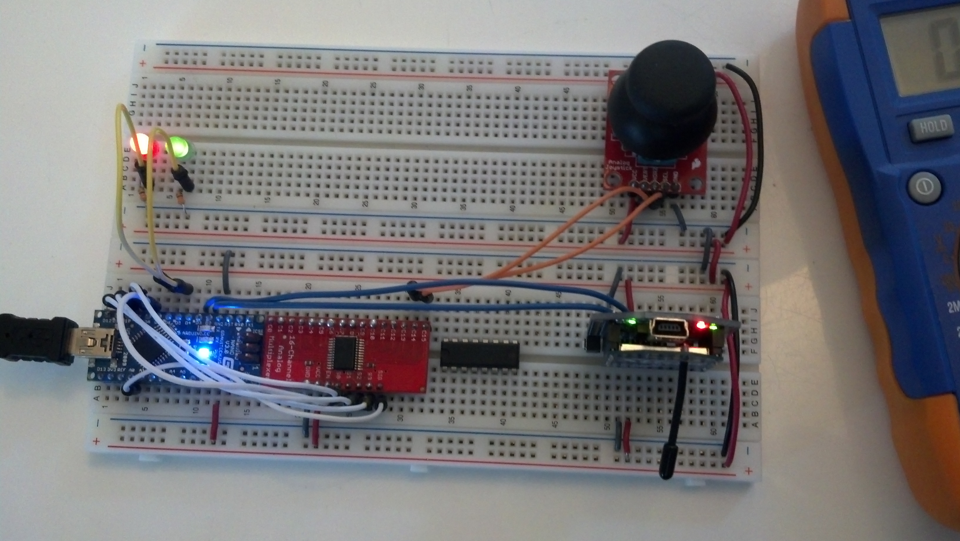
The last system is the controller. It’s an arduino micro hooked up to the same xbee system as seen earlier with a joystick and a multiplexer for more inputs. Here’s a video:
And some pictures:
So basically it receives and sends data to and from the controller as seen in the following code:
//Serial Handshake declaration
#include <string.h> // we'll need this for subString
#define MAX_STRING_LEN 20 // like 3 lines above, change as needed.
const char EOPmarker = '.'; //This is the end of packet marker
char serialbuf[32]; //This gives the incoming serial some room. Change it if you want a longer incoming.

//SoftwareSerial declaration
#include <SoftwareSerial.h>
SoftwareSerial xbee_serial(2, 3);

//Mux control pins declarations
int s0 = 8;
int s1 = 9;
int s2 = 10;
int s3 = 11;
int SIG_pin = 0;

//Shift Register Pins declaration
int SER_Pin = 5; //pin 14 on the 75HC595
int RCLK_Pin = 6; //pin 12 on the 75HC595
int SRCLK_Pin = 7; //pin 11 on the 75HC595
#define number_of_74hc595s 1 //How many of the shift registers - change this
#define numOfRegisterPins number_of_74hc595s * 8 //do not touch
boolean registers[numOfRegisterPins];

//Servo declarations
int left_servo_val;
int rght_servo_val;

//Misc Pin declaration

//inputs
int debug_switch1 = 4;

//outputs
int pot_LED = 5;
int fade_LED = 6;
int debug_switch1_LED = 2;

//Misc Integer Declarations
int joystick_x;
int joystick_y;

int brightness = 0; // how bright the LED is
int fadeAmount = 20; // how many points to fade the LED by

void setup(){
 Serial.begin(9600);
 xbee_serial.begin(9600);

 //mux setup
 pinMode(s0, OUTPUT);
 pinMode(s1, OUTPUT);
 pinMode(s2, OUTPUT);
 pinMode(s3, OUTPUT);
 digitalWrite(s0, LOW);
 digitalWrite(s1, LOW);
 digitalWrite(s2, LOW);
 digitalWrite(s3, LOW);

 //shift register setup
 pinMode(SER_Pin, OUTPUT);
 pinMode(RCLK_Pin, OUTPUT);
 pinMode(SRCLK_Pin, OUTPUT);
 pinMode(0, INPUT);
 clearRegisters();
 writeRegisters();

 //Misc Pin Declarations
 pinMode(pot_LED, OUTPUT);

xbee_serial.print("0,0,0."); // this is very important as it starts of the loop because it makes "xbee_serial.avalible() > 0.
}

void loop(){
 if (xbee_serial.available() > 0) {
 static int bufpos = 0;
 char inchar = xbee_serial.read();
 if (inchar != EOPmarker) {
 serialbuf[bufpos] = inchar;
 bufpos++;
 }
 else {
 serialbuf[bufpos] = 0; //restart the buff
 bufpos = 0; //restart the position of the buff

 handshake();
 }
 }
}

void handshake(){
 //input, recived from vehicle
 //led1.
 analogWrite(pot_LED, map(atoi(subStr(serialbuf, "," , 1)),0,1023,0,255));
 analogWrite(fade_LED, atoi(subStr(serialbuf, "," , 2)));

 brightness = brightness + fadeAmount;
 // reverse the direction of the fading at the ends of the fade:
 if (brightness == 0 || brightness == 255) {
 fadeAmount = -fadeAmount ;
 }

 //output, sent to vehicle
 //joystick1_ledval,joystick2_ledval,fade_LED.
 analogRemap();
 xbee_serial.print(joystick_x); // Value that it sends over the serial
 xbee_serial.print(",");
 xbee_serial.print(joystick_y); //This second byte is for the purpose of the program, it is not being used.
 xbee_serial.print(",");
 xbee_serial.print(brightness);
 xbee_serial.print("."); //EOP marker
 delay(10);
}

void debug_handshake(){

}

void analogRemap(){
 joystick_x = readMux(15);
 joystick_y = readMux(14);
}
char* subStr (char* input_string, char *separator, int segment_number) {
 char *act, *sub, *ptr;
 static char copy[MAX_STRING_LEN];
 int i;

 strcpy(copy, input_string);

for (i = 1, act = copy; i <= segment_number; i++, act = NULL) {

 sub = strtok_r(act, separator, &ptr);
 if (sub == NULL) break;
 }
 return sub;
}

int readMux(int channel){
 int controlPin[] = {s0, s1, s2, s3};
 int muxChannel[16][4]={
 {0,0,0,0}, //channel 0
 {1,0,0,0}, //channel 1
 {0,1,0,0}, //channel 2
 {1,1,0,0}, //channel 3
 {0,0,1,0}, //channel 4
 {1,0,1,0}, //channel 5
 {0,1,1,0}, //channel 6
 {1,1,1,0}, //channel 7
 {0,0,0,1}, //channel 8
 {1,0,0,1}, //channel 9
 {0,1,0,1}, //channel 10
 {1,1,0,1}, //channel 11
 {0,0,1,1}, //channel 12
 {1,0,1,1}, //channel 13
 {0,1,1,1}, //channel 14
 {1,1,1,1} //channel 15
 };

//loop through the 4 sig
 for(int i = 0; i < 4; i ++){
 digitalWrite(controlPin[i], muxChannel[channel][i]);
 }

//read the value at the SIG pin
 int val = analogRead(SIG_pin);

//return the value
 return val;
}

void clearRegisters(){
 for(int i = numOfRegisterPins - 1; i >= 0; i--){
 registers[i] = LOW;
 }
}

void writeRegisters(){
 digitalWrite(RCLK_Pin, LOW);
 for(int i = numOfRegisterPins - 1; i >= 0; i--){
 digitalWrite(SRCLK_Pin, LOW);
 int val = registers[i];
 digitalWrite(SER_Pin, val);
 digitalWrite(SRCLK_Pin, HIGH);
 }
 digitalWrite(RCLK_Pin, HIGH);
}

//set an individual pin HIGH or LOW
void setRegisterPin(int index, int value){
 registers[index] = value;
}
All of the parts listed in this video can be seen here which is the parts list.
That was a huge post! Thanks for reading and leave a comment if you have any questions.


