As this post is more of an update, I won’t be adding any explanations, just giving the python code.
This will read 3 values from the adc and put them into the database “adc_database”. It will put them in the table “adc_input_data_4” in the columns “Channel_1″,”Channel_2” and “Channel_3” respectively.
#!/usr/bin/env python
# -*- coding: utf-8 -*-
import spidev
import time
import MySQLdb
import sys
import RPi.GPIO as GPIO

pin = 26

GPIO.setmode(GPIO.BOARD)
GPIO.setup(pin, GPIO.OUT)

con = MySQLdb.connect('localhost','adc_user','adc_user_pass','adc_database');
cursor = con.cursor()

spi = spidev.SpiDev()
spi.open(0, 0)
count = 0
maxcyclenumber = 5

tmp = "derp"

def readadc(adcnum):
# read SPI data from MCP3008 chip, 8 possible adc's (0 thru 7)
    if adcnum > 7 or adcnum < 0:
        return -1
    r = spi.xfer2([1, 8 + adcnum << 4, 0])
    adcout = ((r[1] & 3) << 8) + r[2]
    return adcout


for _ in range(maxcyclenumber):

	GPIO.output(pin,True)
	cursor.execute("INSERT INTO adc_input_data_4(Channel_1,Channel_2,Channel_3) VALUES('%s','%s','%s')",(readadc(0),readadc(1),readadc(2)) )
	GPIO.output(pin,False)

	count = count+1
	print count
	time.sleep (1)

if count == maxcyclenumber:
	GPIO.cleanup()
	con.commit()
	con.close()
Now everything should be good to go, now for the python.
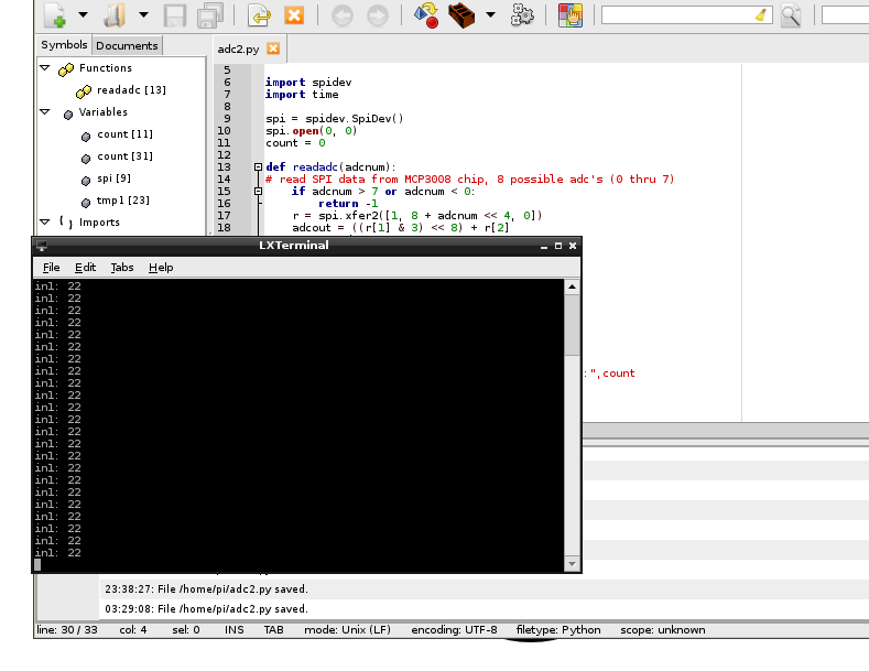
You can debug this any way you like, but my favorite way to do it is using the program geany. I like to start up a VNC server with root so I don’t get into any trouble with the GPIO permissions.
But here’s the program.
#!/usr/bin/python
# -*- coding: utf-8 -*-

import spidev
import time

spi = spidev.SpiDev()
spi.open(0, 0)
count = 0

def readadc(adcnum):
# read SPI data from MCP3008 chip, 8 possible adc's (0 thru 7)
    if adcnum > 7 or adcnum < 0:
        return -1
    r = spi.xfer2([1, 8 + adcnum << 4, 0])
    adcout = ((r[1] & 3) << 8) + r[2]
    return adcout

while True:
    tmp1 = int(round(readadc(0)/10.24))
    print "in1:",tmp1
    count = count +1
    time.sleep(0.2)
And that’s pretty much it, the result should look something like this:
If you’re a long time follower of the blog, than you may notice that it looks like I’m backtracking here. Let me go over the differences between the two systems I’ve developed.
The one I “finished” a few months ago can be found here. While the code is “good” and it works well for what it does, there are a few inherent problems with it. The first being that it has to have a computer to be used. The second being that the computer running the intermediate program has to be extremely fast, so it’s not totally feasible for field use. It would also be very hard for it to go wireless, but I had built that groundwork in so it could happen.
The one I’m working on now doesn’t require a computer as an intermediate, and is going to be totally wireless as from the start.
This morning I finished the handshake data exchange over xbee. Right now it’s just dimming a few LED’s but if you take a peek at the following code, it’s very expandable.
Here’s the working code:
#include <SoftwareSerial.h>
SoftwareSerial xbee_serial(2, 3);
#include <string.h> // we'll need this for subString
#define MAX_STRING_LEN 20 // like 3 lines above, change as needed.

int in_LED = 10;
int out_LED = 11;

int input = 2;

int sendval;


//serial stuff
const char EOPmarker = '.';  //This is the end of packet marker
char serialbuf[32]; //This gives the incoming serial some room. Change it if you want a longer incoming.

void setup(){
  pinMode(in_LED, OUTPUT);
  pinMode(out_LED, OUTPUT);
  pinMode(input, INPUT);

  Serial.begin(9600);
  xbee_serial.begin(9600);

  xbee_serial.print("0,0,0."); // this is very important as it starts of the loop because it makes "xbee_serial.avalible() > 0.
}

void loop(){
  if (xbee_serial.available() > 0) {
    static int bufpos = 0;
    char inchar = xbee_serial.read();
      if (inchar != EOPmarker) {
        serialbuf[bufpos] = inchar;
        bufpos++;
      }
      else {
        serialbuf[bufpos] = 0; //restart the buff
        bufpos = 0; //restart the position of the buff

        Serial.println(atoi(subStr(serialbuf, "," , 1)));
        analogWrite(in_LED, atoi(subStr(serialbuf, "," , 1)));

         sendval = map(analogRead(input), 0, 1023, 0, 255);
         xbee_serial.print(sendval); // Value that it sends over the serial
         xbee_serial.print(",");
         xbee_serial.print("100"); //This second byte is for the purpose of the program, it is not being used.
         xbee_serial.print("."); //EOP marker
         analogWrite(out_LED , sendval);

    }
  }

  //delay(10);
}

char* subStr (char* input_string, char *separator, int segment_number) {
 char *act, *sub, *ptr;
 static char copy[MAX_STRING_LEN];
 int i;

 strcpy(copy, input_string);

for (i = 1, act = copy; i <= segment_number; i++, act = NULL) {

 sub = strtok_r(act, separator, &ptr);
 if (sub == NULL) break;
 }
 return sub;
}
#include <SoftwareSerial.h>
SoftwareSerial xbee_serial(2, 3);
#include <string.h> // we'll need this for subString
#define MAX_STRING_LEN 20 // like 3 lines above, change as needed.

int in_LED = 10;
int out_LED = 11;

int input = 2;

int sendval;


//serial stuff
const char EOPmarker = '.';  //This is the end of packet marker
char serialbuf[32]; //This gives the incoming serial some room. Change it if you want a longer incoming.

void setup(){
  pinMode(in_LED, OUTPUT);
  pinMode(out_LED, OUTPUT);
  pinMode(input, INPUT);

  Serial.begin(9600);
  xbee_serial.begin(9600);

  xbee_serial.print("0,0,0.");
}

void loop(){
  if (xbee_serial.available() > 0) {
    static int bufpos = 0;
    char inchar = xbee_serial.read();
      if (inchar != EOPmarker) {
        serialbuf[bufpos] = inchar;
        bufpos++;
      }
      else {
        serialbuf[bufpos] = 0; //restart the buff
        bufpos = 0; //restart the position of the buff

        Serial.println(atoi(subStr(serialbuf, "," , 1)));
        analogWrite(in_LED, atoi(subStr(serialbuf, "," , 1)));

         sendval = map(analogRead(input), 0, 1023, 0, 255);
         xbee_serial.print(sendval); // Value that it sends over the serial
         xbee_serial.print(",");
         xbee_serial.print("100"); //This second byte is for the purpose of the program, it is not being used.
         xbee_serial.print("."); //EOP marker
         analogWrite(out_LED , sendval);

    }
  }

  delay(10);
}

char* subStr (char* input_string, char *separator, int segment_number) {
 char *act, *sub, *ptr;
 static char copy[MAX_STRING_LEN];
 int i;

 strcpy(copy, input_string);

for (i = 1, act = copy; i <= segment_number; i++, act = NULL) {

 sub = strtok_r(act, separator, &ptr);
 if (sub == NULL) break;
 }
 return sub;
}
Basically this is a proof of concept. The transmitter is sending a line of data very similar to the one that will be sent by the final controller (as seen in the controller code) the receiving end with be receiving in the same way the vehicle code does (same as above).
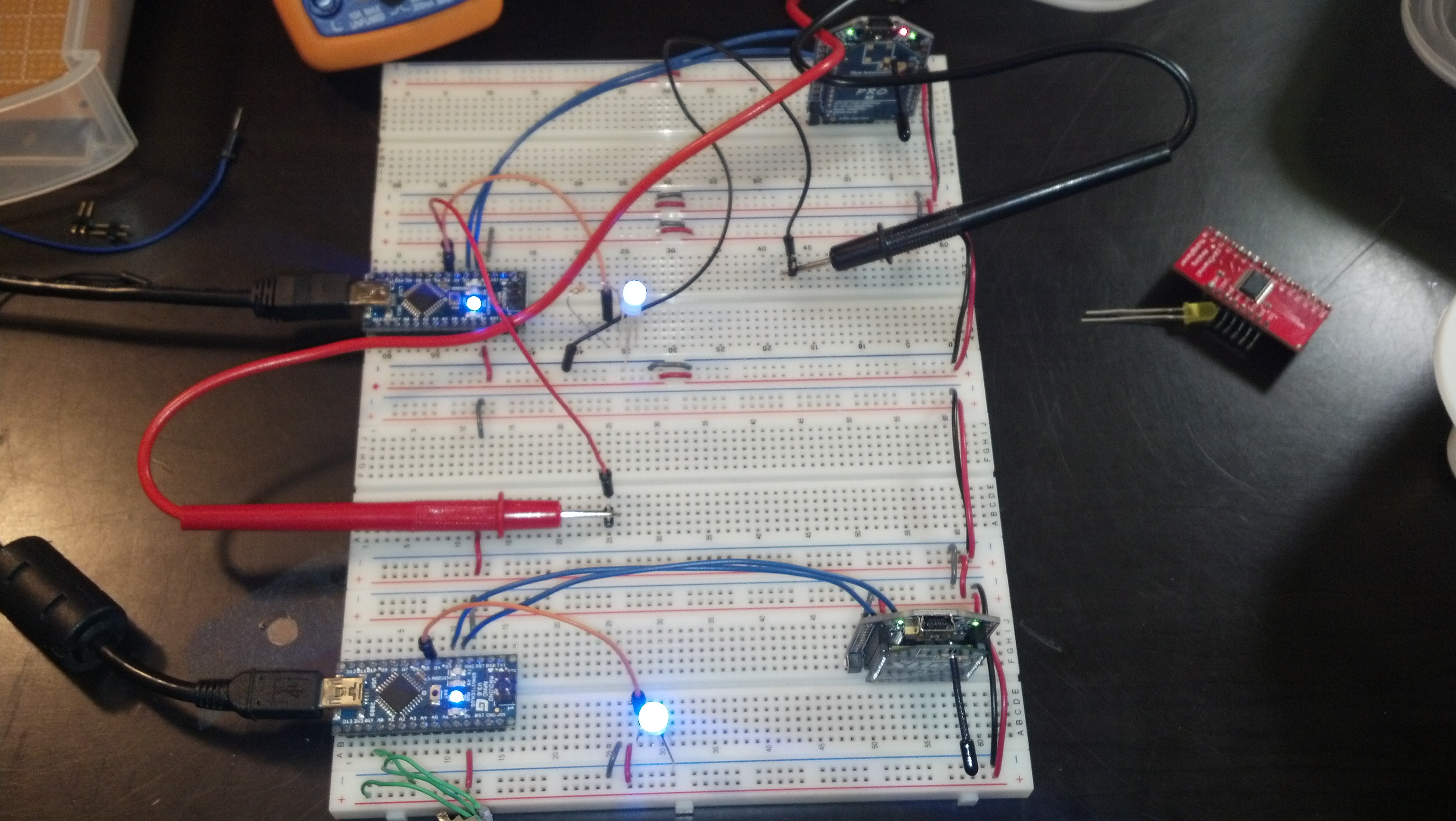
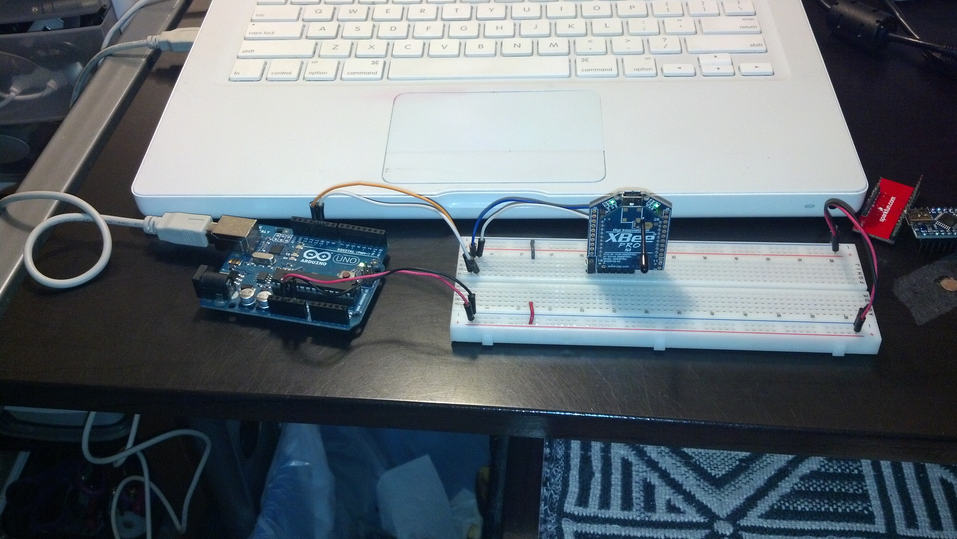
Here are a few pictures, this first one is a top down view of my prototyping area:
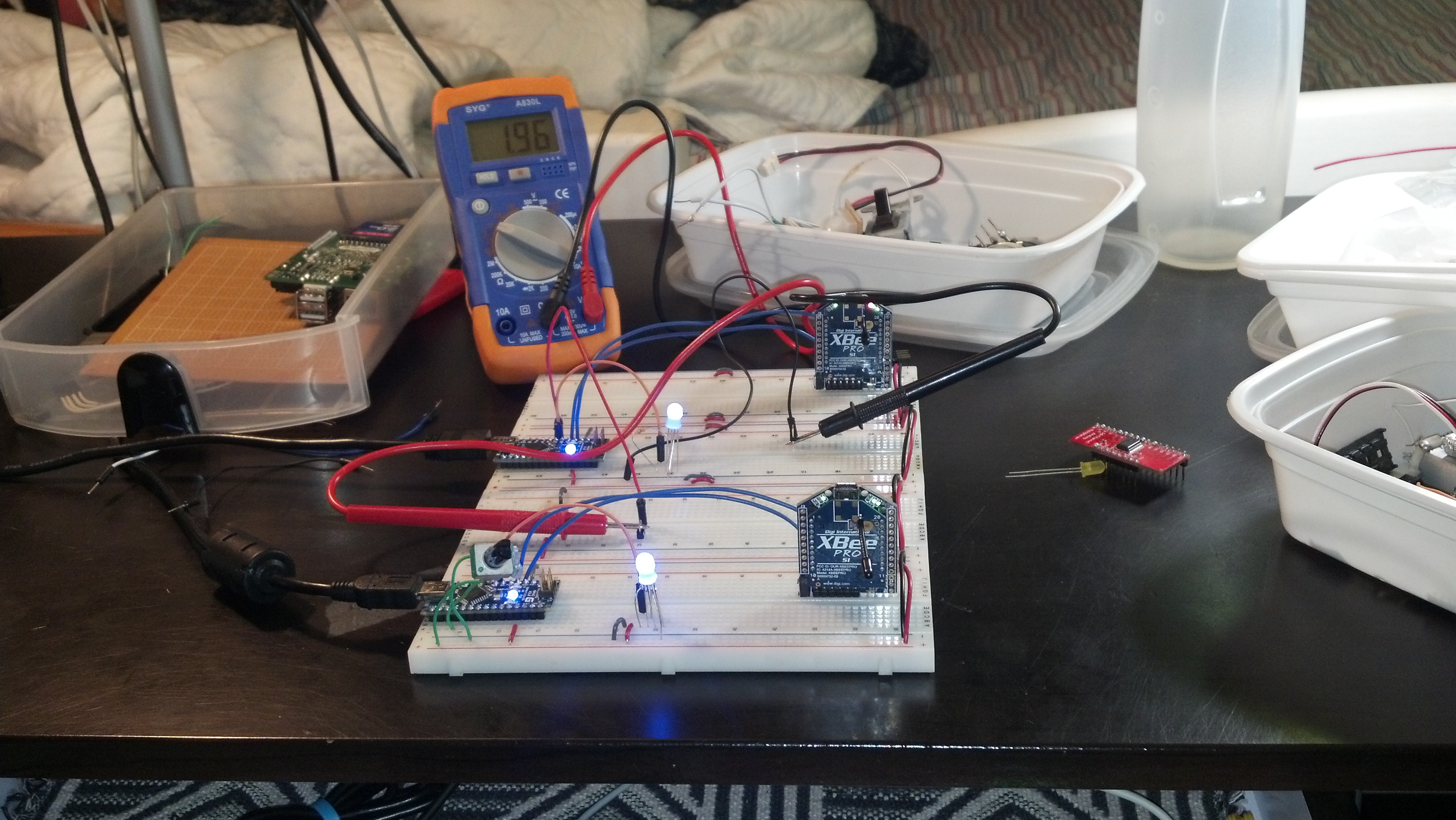
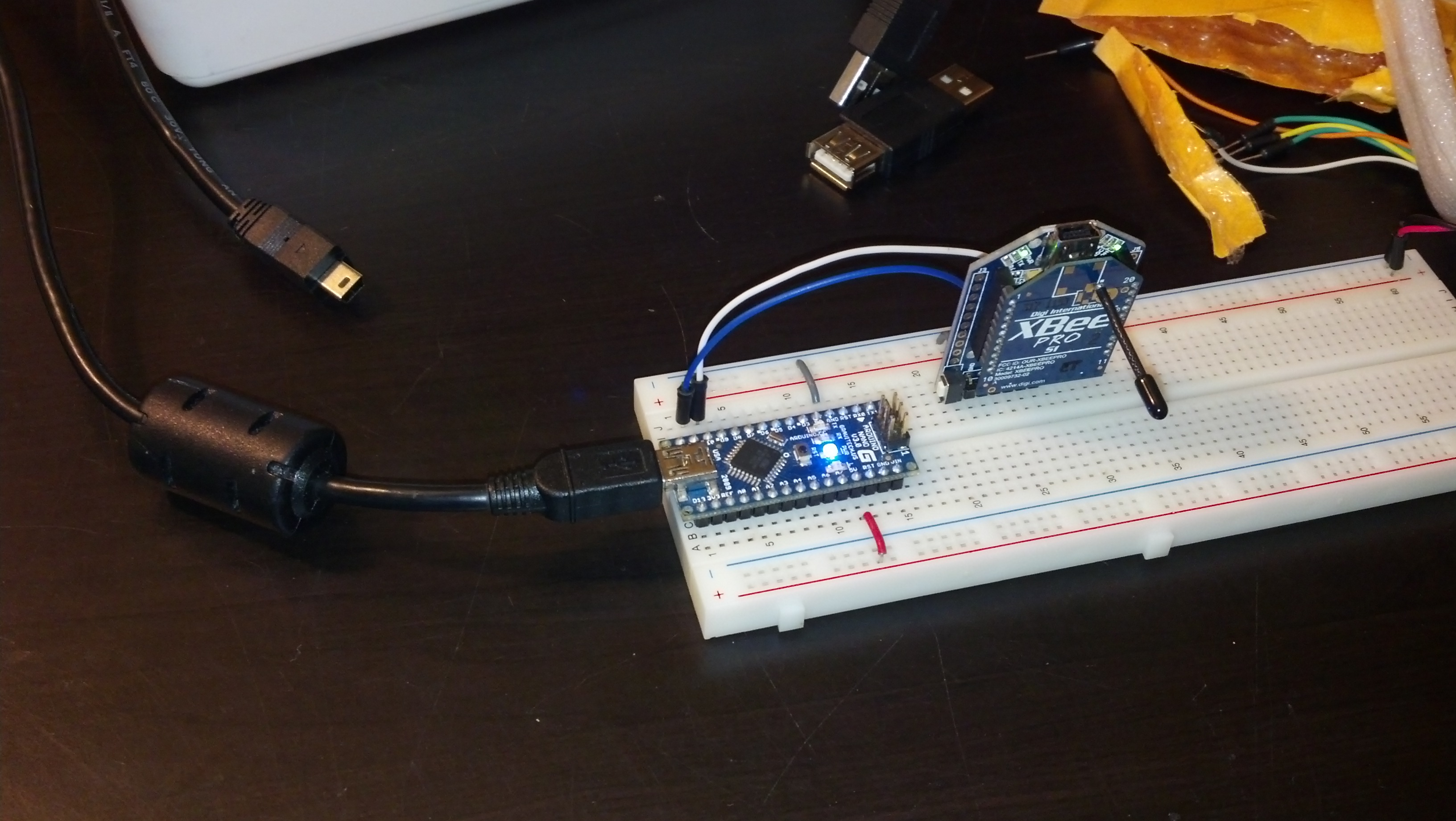
This second one shows all components involved:
This is the code running on the transmitter side, the side with the pot that’s transmitting it’s analog value:
</div>
<div>

#include <SoftwareSerial.h>
SoftwareSerial xbee_serial(2, 3);

int pot_1 = 0;
int LED_1 = 5; //this will serve as an LED to compare to
int sendval;

void setup(){
 pinMode(pot_1, INPUT);
 pinMode(LED_1, OUTPUT);
 Serial.begin(9600);
 xbee_serial.begin(9600);
}

void loop(){
 Serial.println(analogRead(pot_1));
 sendval = map(analogRead(pot_1), 0, 1023, 0, 255);
 xbee_serial.print(sendval); // Value that it sends over the serial
 xbee_serial.print(",");
 xbee_serial.print("100"); //This second byte is for the purpose of the program, it is not being used.
 xbee_serial.print("."); //EOP marker
 analogWrite(LED_1,sendval);
 //delay(100);
}
This second half is on the receiving end. It may seem way overkill for what it does, but it’s all expandable to a pretty much infinite amount of data to be transmitted. For an example of what it’s capable of see this video:
</div>
<div>

#include <SoftwareSerial.h>
SoftwareSerial xbee_serial(2, 3);
#include <string.h> // we'll need this for subString
#define MAX_STRING_LEN 20 // like 3 lines above, change as needed.

int LED_1 = 5;

int led_val;

//serial stuff
const char EOPmarker = '.'; //This is the end of packet marker
char serialbuf[32]; //This gives the incoming serial some room. Change it if you want a longer incoming.

void setup(){
 pinMode(LED_1, OUTPUT);
 Serial.begin(9600);
 xbee_serial.begin(9600);
}

void loop(){
 if (xbee_serial.available() > 0) {
 static int bufpos = 0;
 char inchar = xbee_serial.read();
 if (inchar != EOPmarker) {
 serialbuf[bufpos] = inchar;
 bufpos++;
 }
 else {
 serialbuf[bufpos] = 0; //restart the buff
 bufpos = 0; //restart the position of the buff

Serial.println(atoi(subStr(serialbuf, "," , 1)));
 analogWrite(LED_1, atoi(subStr(serialbuf, "," , 1)));
 }
 }
}

char* subStr (char* input_string, char *separator, int segment_number) {
 char *act, *sub, *ptr;
 static char copy[MAX_STRING_LEN];
 int i;

 strcpy(copy, input_string);

for (i = 1, act = copy; i <= segment_number; i++, act = NULL) {

 sub = strtok_r(act, separator, &ptr);
 if (sub == NULL) break;
 }
 return sub;

}
So the first round of parts have come in for the plane, including the Xbees and the UartSBee V4s. My life is going to be very scattered over the next 4 or 5 months, so I’m going to be making frequent rudimentary posts for my own benefit.
Here’s a video:
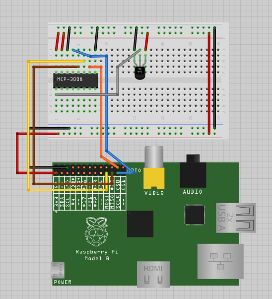
First thing’s first I want to outline how everything’s connected.
The first xbee is connected to the first UartSBee which is connected to an Ardunio Uno which is connected to the first computer which has the console open and is looking at the serial stream at 9600 baud. The xbee is connected to the uno via Software Serial which is detailed in the code below. Here’s a picture:
The second setup is identical, except i’m using an Ardunio nano.
Here’s the code, I’m using the SoftwareSerial library to accomplish this. Both Arduinos are running the same thing.
</p>
#include <SoftwareSerial.h>

SoftwareSerial mySerial(10, 11); // RX, TX

void setup()
{
 // Open serial communications and wait for port to open:
 Serial.begin(9600);
 while (!Serial) {
 ; // wait for serial port to connect. Needed for Leonardo only
 }
 Serial.println("Goodnight moon!");

// set the data rate for the SoftwareSerial port
 mySerial.begin(9600);
 mySerial.println("Hello, world?");
}

void loop() // run over and over
{
 if (mySerial.available())
 Serial.write(mySerial.read());
 if (Serial.available())
 mySerial.write(Serial.read());
}
<p style="text-align: left;">
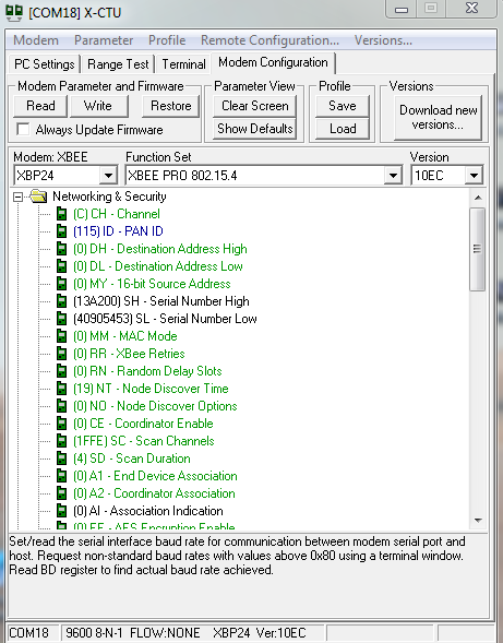
Here are a few pictures of the X-TCU setup. The baud is at 9600 and the pan ID is 115. The UartSbee itself is running at 115200 baud connected to the computer.