PiScanner – GPIO output | Documentation [Research]

I will need to illuminate the “subjects” that I will be capturing. In order to do this, I will eventually need to set some pin high. Weather it be that it sets of a camera flash or turns on some lights for a second, it will need to happen down the line.


Like all of my “research” I mostly googled around / plugged in code until something worked. I came back with these links:

http://www.youtube.com/watch?v=q_NvDTZIaS4

https://docs.google.com/file/d/0B2-00drKdqF0V09YSHgxcTEtelk/edit

http://hackaday.com/2012/06/17/using-the-gpio-pins-on-a-raspberry-pi/


Basically you need to install the Raspberry Pi GPIO, Import and use the RPi GPIO

1. Download the library:

$ wget http://pypi.python.org/packages/source/R/RPi.GPIO/RPi.GPIO-0.2.0.tar.gz#md5=0fc4bfa6aabc856b0b75252a40ac75cc

2. unzip the file:

$ sudo tar -zxvf RPi.GPIO-0.2.0.tar.gz

you can remove the .tar.gz at that point

3. get into the directory you just created:

$ cd  RPi.GPIO-0.2.0

4. The devs included a great install script with this package, run it to install with:

$ sudo python setup.py install

Now you should see a bunch of text in the command line. I have no idea why, but my first run of this command didn’t “take” but I ran it again and now it works great.


To use this, you need to know what pins correspond to pins on the RPi. You can google this yourself.


Now we get writing code. I’m using a graphical python editor called geaney which comes pre-loaded with squeeze.


To blink pins 11 and 13, use and run this python script.

You can see the plaintext version of that script here.


Essentially i’m trying to mimic things I’ve done with an Arduino for some time.

Maybe later today (if I can somehow find a 100ohm resistor) I’ll work on using inputs. I have a PIR motion sensor with me, but I neglected to bring the proper resistor to use it. I do have tack switches and resistors for those, which I could use to mimic the motion detector, but I don’t think that would be as cool.


PiScanner | Basics [Research]

So I’ve determined that there will be 2 parts to this project.


1. Be able to take a picture with a USB webcam via command line.

I’ve landed on a program called fswebcam. I found it via a few google searches. I installed it by using the command:


$ sudo apt-get install fswebcam 


I used the:


$ man fswebcam


command to “derive” how to use the program, but essentially I made a


config file


that the program can execute. You can run the program with the above configuration by typing:


fswebcam -c /home/user/Pictures/picture.conf //the location of the .conf file should be wherever you put it, so the code after the space after the -c will be different for you. 


This will produce an image from your webcam in the location you specified in the picture.conf file.


Other info can be found here: http://www.r3uk.com/index.php/home/38-software/100-webcam-capture-using-fswebcam


I installed all of this on my server and got the below image. This is what the laptop running this website sees!


2. Write a python (I’ve decided to go with python because I’ve never used python before, it will be good to learn something new. And because there is already a library for controlling the GPIO pins on the RPi baked into the language.) script that can sense weather or not this sensor‘s alarm pin is pulled low. At that point, the script should then execute the above bash command and take a picture. After that, that photo should be moved somewhere to do something, but I don’t know what that will be yet. It will probably be uploaded to a secure location on my server and then I will have it email me if at the end of the night, something shows up.

http://pypi.python.org/pypi/RPi.GPIO


PiScanner | Project Execution [Declaration]

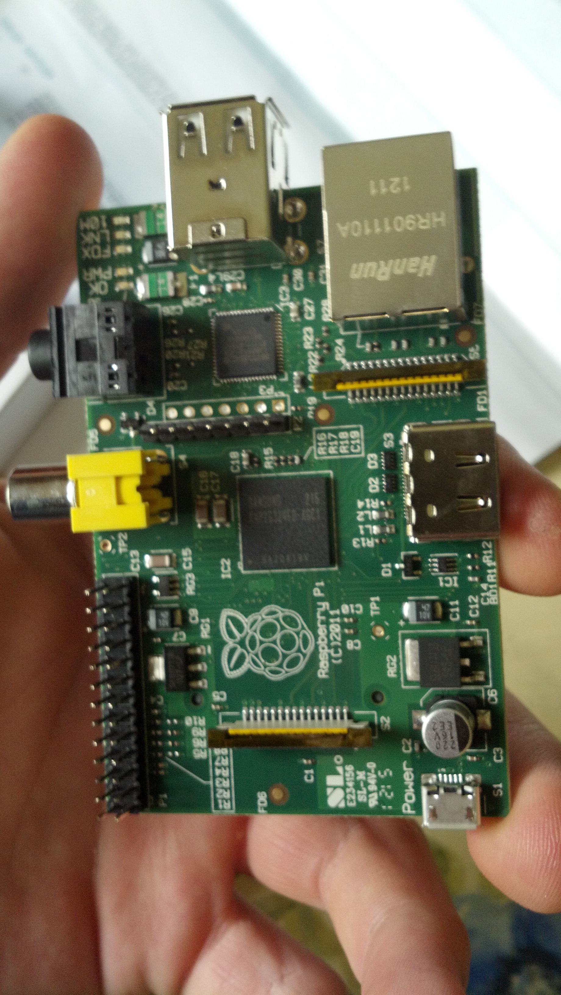
Raspberry Pi

Hello Hello Hello!

//If you just want to see the PiScanner Progress, skip the next 2 blocks

So, you may have noticed an absence of recent posts on this website. This is due to a few factors but the main one is a lack of focus. Not a lack of focus in a multi-tasking sense, but in a sort of literal sense. I’ve got foggy fragments of ideas, but no concrete ideas that are feasible. I think that the introduction of the “Project Execution” prefix in the title of this post (and hopefully all of my other project-based posts) will keep me “responsible” in regard to things I try and undertake.

There will be 5 steps for each project.

  1. Declaration
  2. Research
  3. Documentation
  4. Report feasibility [1] (This is where we will learn if the project is possible or not, and if not why.), Share all code [2] Take Lots of pictures [3]
  5. Demonstrate / Distribute
Now to PiScanner
After Receiving my Raspberry Pi :

Raspberry Pi

In the mail recently, I’ve got a whole new area of new more powerful computer science to enter into, and I think the PiScanner is the best way to do this.


The PiScanner will be a program that will identify motion using a PIR detector in junction with the GPIO pins, capture an image using a webcam or other camera compatible with the ports on the board, and then upload that image to a server to be viewed via rss.


This will be great for my backyard at night, it’s like animal planet out there this time of year and it will teach me a bunch of new things upon completion.


Check back for more!


A comprehensive guide to controlling a lamp via the internet on any web enabled device.

Yay Chinese knockoffs!

Hello! sorry about my absence, I’ve been very busy with school/baseball over the past few weeks, but summer is soon, and I’ll be updating with a higher frequency once that happens.

So. you’ll need a few things in order to make sure this whole process works.

1. Multiple ethernet connections.

2. An Arduino and a compatible wiznet device (ethernet shield)

Yay Chinese knockoffs!

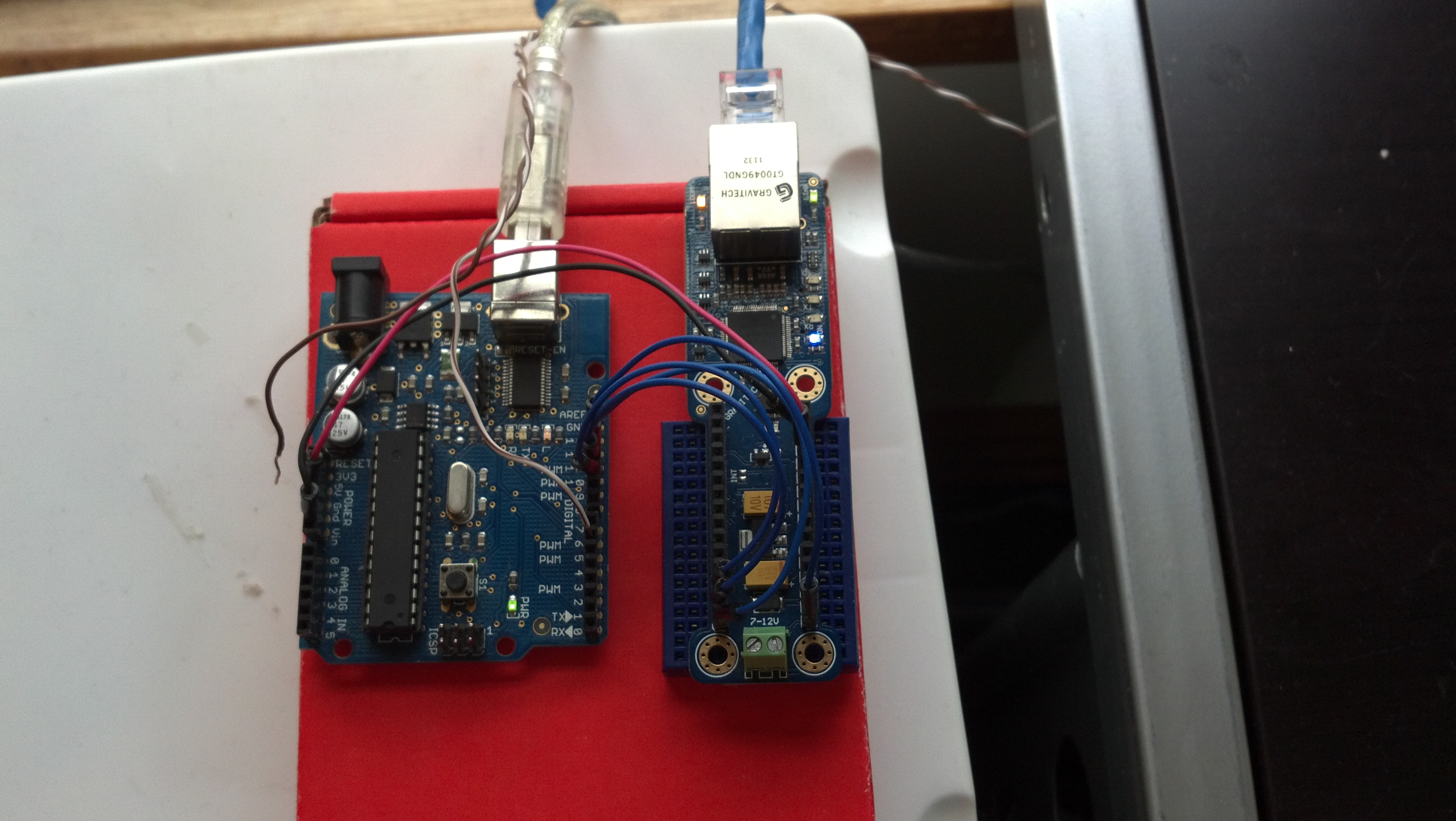
Here I’m using an arduino knockoff I got 2 years ago when I first got into hobby electronics, and an “ETHERNET 4 NANO” by gravitech. I didn’t want to permanently implement my arduino nano, but I still wanted to be able to do the project. It’s powered by 5v from my computer (well from a powered hub) and the brown striped wire goes to the + on the powerswitch tail II. The blue cable is ethernet.

3. A webserver with php installed on it. (Mine’s just LAMP’d)

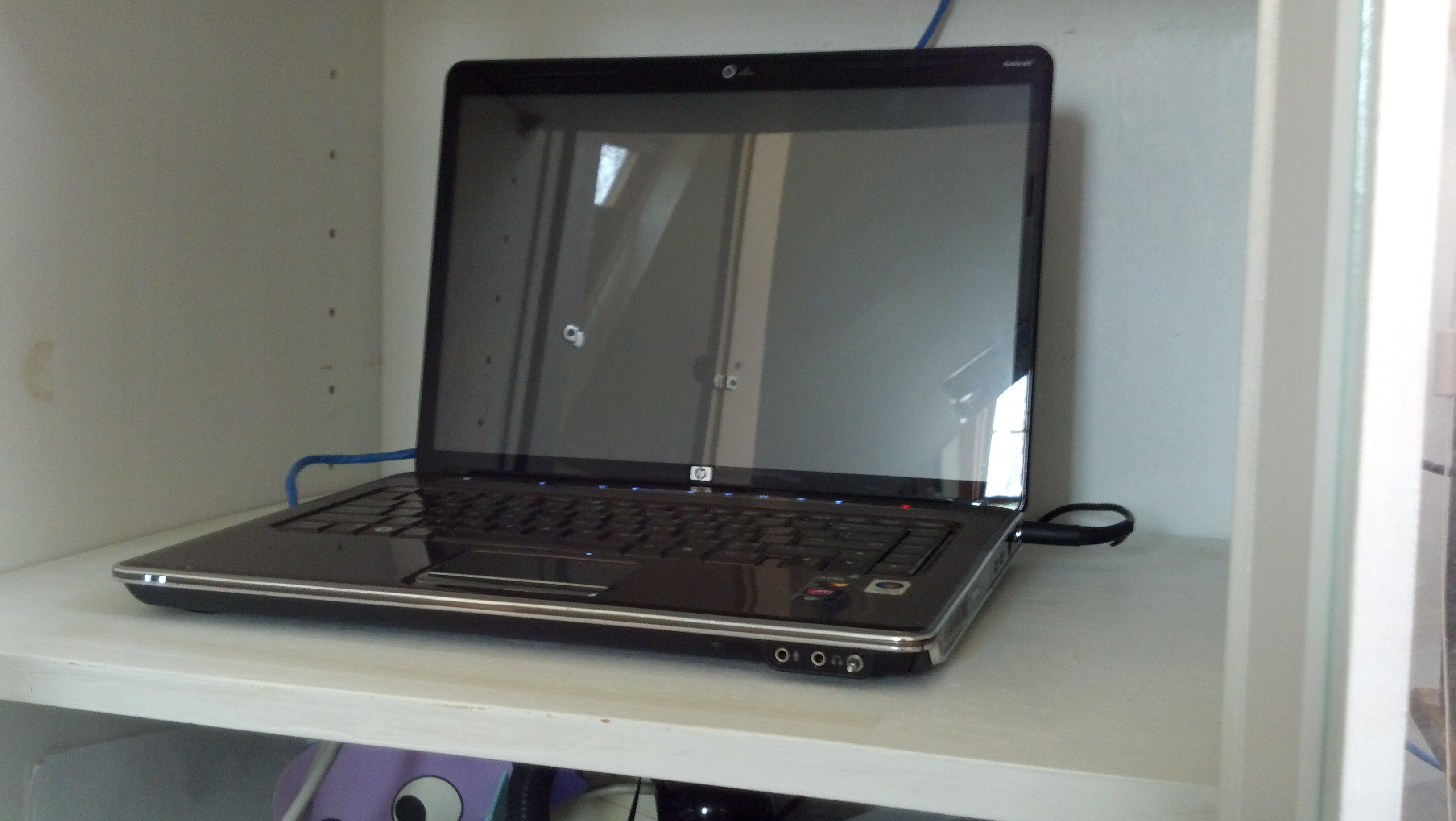
This is the important part. The arduino is accessing a .php document on the server to tell weather or not the lamp should be on. The UI is also hosted out of the servo. That laptop is my old HP laptop that I’ve had for almost 6 years, it’s now got ubuntu 10.04 LTS on it and it’s been LAMP’d among other things.

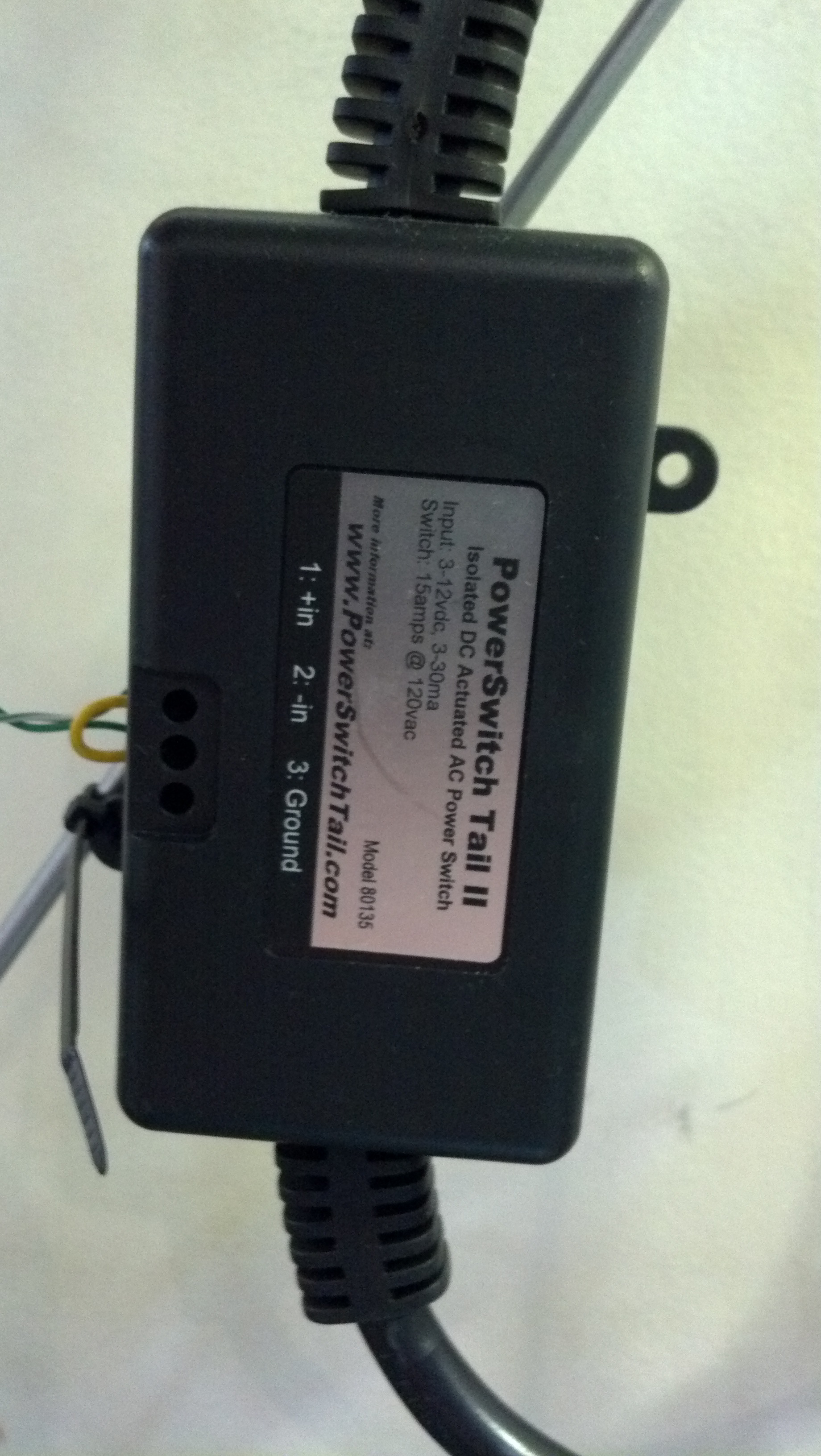
4. Something that can SAFELY switch line voltage. (I’m using a powerswitch tail II, because I really don’t want to get killed, and it’s also very simple – if you’re using naked relays, please for the love of god, be careful with line voltages.)

This thing is a beast. I can drive it via 5v easily, and it switches line like a champ. It’s been in constant use since my last post about home automation.

START OF GUIDE

1. So first, we need to hook up the shield, the arduino and the PSTII. It’s really easy.

2. Get linux on the computer you want to run the server out of. I made a video a long time ago back when I was first getting into linux. The installation process is still the same, you can find that video here.

3. Install various programs your server. First things first, you have to install openssh by running the command:

sudo apt-get install openssh

This will make the server headless, and it will enable you to access the server via command line. Specifically through PuTTY for windows. You can then ssh to your server which is key. You then need to install LAMP by running the command:

sudo apt-get install LAMP

This will install PHP on your server as wells apache and mysql. The two ladder objects are not essential for this project, but if you are going to use the server for other things, I strongly recommend you get them as well. The install process is very easy, just make sure you WRITE EVERY USERNAME AND PASSWORD YOU USE DOWN. I’ve had to reinstall several times before I learned my lesson on this.

After you are done with that, install vim by running the command:

sudo apt-get install vim

Vim is a text editing program for linux. You also need to get pure ftp to upload and download files from your server. Get it by running the command:

sudo apt-get install pure-ftpd

Congrats! you are now an owner of a very powerful linux server. Wasn’t that easy?

4. Upload the call.php, res.php documents to your server.

This is the call.php text, you just need to make it into a .php document and upload it to the server. This document creates a form that the user accesses to turn the lamp on and off.

This is the res.php. It is what the user is taken to once they have entered the information in the call.php.

If you walk though the code. You will see that once the correct password gets entered, the res.php document creates a functioning document stat.php. This is the same document that the arduino reads, and compares to.

5. You need to upload the arduino code.

Here it is, upload it to your board with the shield attached, and everything should work. Access the call.php via your server, and go through the process.

At this point everything should work, please let me know if it doesn’t in the comments.

3 Pins Controlling 14 (Shift Registers)

The Breadboard

Sorry I haven’t been posting in the last few weeks, I’ve been pretty busy with school / swimming.

The Youtube video demonstrating the final product.

Anyways! I’ve set aside my home automation project and picked up a few of these shift registers: the 74hc595 by TI, seen here:

As seen in the video above, I’m controlling 14 led’s using two of the 74hc595s and and 3 pins on an Arduino Uno.

The Breadboard

The program uses a for loop and cycles through the 14 pins on the registers. That code can be found here. Thanks for reading, check back soon for updates on the home automation project.

Progress on Web Controlled Arduino (A line-voltage Powered Lamp now!)

http://www.youtube.com/watch?v=5m6KFgQ3HJQ

Watch the video above for context. In summation though, what we have is basically an arduino that fetches a string from a php file on my server, interprets  it, and compares it to a predetermined char array.

In the future, this WILL have a GUI that can be controlled from a website and do the lamp that way from any source inducing mobile (maybe even twitter!).

Source-wise the code isin’t very well commented but the Arduino is here, and the php is here. A word of warning: unless you want me to be able to control a leigon of lamps across the world, I would suggest changing ip addresses / filepaths on the Arduino side.

On another side note all of my sources for stuff I write about on this blog here

Beginnings of a web controlled Arduino

So I’ve made a bit of progress with the project that I’ve been undertaking lately. I’m trying to control a powerswitch tail from an arduino via the internet using the Ethernet shield and a PHP server. Right now I can edit a the name of a string (well, echo) in putty on a document on my PHP server (the very same LAMP that’s allowing me to type this post!) and have the Arduino decode that string (echo) and print it back to the serial console at 9600 baud.   You can grab the source for the Arduino here and the PHP script here See comments in the arduino code for notes about setup. Also deduction is your friend 🙂 Happy programming!