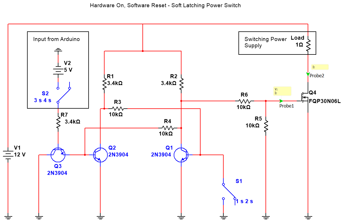
This circuit aims to replace a traditional toggle switch for switching large amounts of current. Instead of the bulky and expensive traditional toggle switch, this circuit allows for a cheap pushbutton, and a few transistors and resistors to be used and have the same effect.
For my application, I wanted a way to have the circuit draw very little curren
t when in the off state, be able to be powered on with a pushbutton, and then turned off through software on the Arduino.
Here is the circuit diagram:
Here’s a video of the circuit in operation:
The code running on the Arduino is very simple:
int button = 3;
int led = 2;

void setup() {
  pinMode(button, INPUT);
  pinMode(led, OUTPUT);

  digitalWrite(led, LOW);
}

void loop() {
  if (digitalRead(button)) {
    digitalWrite(led, HIGH);
  }
}
I’m constantly loosing the remote for my RGB LED strip lights, and I have a few days for spring break, time to get hacking. Here’s a demo and explanation video:
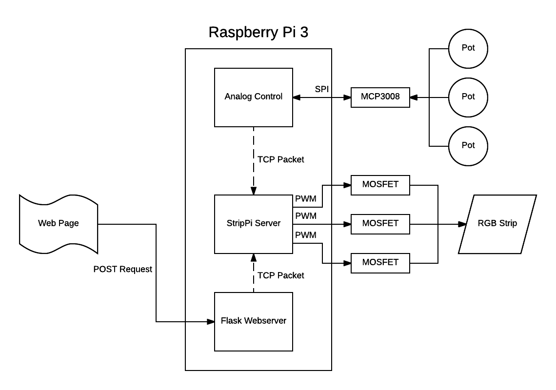
I don’t mention it in the video, but the cool part of this project is how the different processes communicate with each other. Rather than interacting with the different processes through pipes, or something like stdin, I’ve decided to use a TCP websocket server:
Processes on the device send RGB values to the Strip Server via a TCP packet. This very very easy to implement, and almost all of the hard work is taken care of via the socketserver module included in python3. This also allows for interactions with that main process (the StripPi Server process) to take place off of the Raspberry Pi as well. I plan on writing an Alexa integration for this project moving forward, and this should make that a lot easier.
The analog to digital conversion is handled by an MCP3008, exactly the same way as I did it here.
For another project I’m currently working on, I need a way to control multiple microcontrollers in a multi-point, multi-drop network configuration. Luckily, we live in amazing times. As I write this, you you can buy a fully assembled breakout board for the MAX485 chip from Maxim Integrated for a mere $0.45 USD shipped from China.
RS485 is an old protocol, but is the logical next step for devices I’m already communicating with via RS232. For this example, I’m using 4 Arduino boards of various types.
An Arduino Micro as the master
2 Slave Arduino Leonardos
1 Slave Arduino Pro Mini (5v)
Here is a video of the setup:
The schematic is really straightforward as well. The only tricky bit is that I’m using a software serial port on each of the Arduinos for ease of debugging. Here’s a schematic:
The code to acomplish this is really intuitive as well.
Here is the code for the master Arduino:
#include <SoftwareSerial.h>

int MAX485_Receiver_Output_PIN = 10;
int MAX485_Driver_Input_PIN = 11;
int MAX485_Driver_Output_Enable_PIN = 12;

int debug_led = 13;

SoftwareSerial software_serial (MAX485_Receiver_Output_PIN, MAX485_Driver_Input_PIN); // RX, TX

void setup()
{
  Serial.begin(9600); // begin hardware serial
  software_serial.begin(9600); // begin software serial

  pinMode(MAX485_Driver_Output_Enable_PIN, OUTPUT);
  digitalWrite(MAX485_Driver_Output_Enable_PIN, HIGH); // this disables Receiver Output Enable and enables Driver Output Enable
}

void loop()
{

  byte to_send = 0; // declare the byte to be sent to the slaves though, init as 0
  int rate;

  while (true)
  {
    // invert the byte to be sent
    if (to_send == 1) to_send = 0;
    else if (to_send == 0) to_send = 1;

    Serial.print("Sending: ");
    Serial.println(to_send);

    digitalWrite(debug_led, to_send);

    rate = map(analogRead(5), 0, 1023, 0, 1000);

    software_serial.write(to_send); // send our byte out to the MAX485

    delay(rate);
  }
}
This is the code for the slave Arduinos:
#include <SoftwareSerial.h>

int MAX485_Receiver_Output_PIN = 10;
int MAX485_Driver_Input_PIN = 11;
int MAX485_Driver_Output_Enable_PIN = 12;

int debug_led_PIN = 9;

SoftwareSerial software_serial (MAX485_Receiver_Output_PIN, MAX485_Driver_Input_PIN); // RX, TX

void setup()
{
  software_serial.begin(9600); // begin software serial

  pinMode(MAX485_Driver_Output_Enable_PIN, OUTPUT);
  digitalWrite(MAX485_Driver_Output_Enable_PIN, LOW);

  pinMode(debug_led_PIN, OUTPUT);

}

void loop() // run over and over
{
  byte k;

  if (software_serial.available() > 0) // make sure there is something to read
  {
    k = software_serial.read(); // read in a single byte from the serial port
    digitalWrite(debug_led_PIN, k);
  }
}
#include <SoftwareSerial.h>
int MAX485_Receiver_Output_PIN = 10;
int MAX485_Driver_Input_PIN = 11;
int MAX485_Driver_Output_Enable_PIN = 12;
int debug_led_PIN = 9;
SoftwareSerial software_serial (MAX485_Receiver_Output_PIN, MAX485_Driver_Input_PIN); // RX, TX
void setup()
{
software_serial.begin(9600); // begin software serial
pinMode(MAX485_Driver_Output_Enable_PIN, OUTPUT);
digitalWrite(MAX485_Driver_Output_Enable_PIN, LOW);
pinMode(debug_led_PIN, OUTPUT);
}
void loop() // run over and over
{
byte k;
if (software_serial .available() > 0) // make sure there is something to read
{
k = software_serial.read(); // read in a single byte from the serial port
digitalWrite(debug_led_PIN, k);
}
}
In subsequent posts, things will start getting more advanced. For now however this should be enough to start from scratch.
In the end, it all turned out really well. Painting it white and using a white print stand was a good insight, the light reflects around the box pretty well for how few LEDs are in use.
The software flow chart has changed slightly. I removed the speaker as it wasn’t loud enough and added software debouching for the pushbutton interrupt service routine. Here’s that most recent version:
The interesting parts of the code are the cookResin function as well as the main loop of the Arduino:
void loop() {
  digitalWrite(BUTTONLED_pin, HIGH);
  displayStaticState(0);
  if (BPRESSED == true) {
    cookResin(14400);
  }
}

void cookResin(unsigned long MAXTIMER){
  unsigned long SECTIMER = 0;

  writeLCDLines("CURING TIME REM:", "H:MM:SS  -:--:--");

  fadeLEDs(1,1);

  while ((SECTIMER < MAXTIMER) && (BPRESSED)) {
    digitalWrite(BUTTONLED_pin, HIGH);

    String part0 = String("H:MM:SS  ");
    String part1 = secToHuman(MAXTIMER - SECTIMER);
    String line1 = part0 + part1;
    lcd.setCursor(0, 1);
    lcd.print(line1);

    int DMILSECTIMER = 0;
    while ((DMILSECTIMER < 10) && (BPRESSED)){
      digitalWrite(BUTTONLED_pin, HIGH);
      Alarm.delay(100);
      //Alarm.delay(1);
      DMILSECTIMER++;
    }
    SECTIMER++;
  }

  if (BPRESSED == false){
    //start of cancelled cure end

    displayStaticState(2);

    fadeLEDs(0,1);


    delay(1000);
    BPRESSED = false;

    //end of cancelled cure end
  } else {
    //start of successful cure end

    displayStaticState(1);

    fadeLEDs(0,1);

    delay(1000);
    BPRESSED = false;

    //end of sec cure end
  }

  return;

}
Again, this all should all be explained by the flow chart. The full source can be found at the bottom of this post.
The circuit schematic hasn’t changed at all since this post, here’s a fritzing of what’s going on:
Super simple, basically a screen and a button. The parts to make this are here:
Assembly is super straight forward, if you’re trying to build one and have any questions, let me know!
This past school year I too several classes related to 3D modeling. One class in particular, a class based around SolidWorks. I hadn’t really been able to use the software again, not having the tools to actually execute. MADE@MassChallenge really has the whole kit, 3D Printers, a 40W Laser Cutter etc. All the tools of a hackerspace as a part of my job. Here’s a “finished” model of the system:
The frame is held together with a series of L brackets and machine screws from home depot
The front opening is secured with two metal hinges from home depot
There were a couple 3D modeled components as well:
The four feet
I ended up gluing these down with hot glue even though they have cuts for screws. In the end, it wasn’t worth it to use more screws and add more complexity.
There is a frosted acrylic sheet inserted in the top. One of the goals of this project was to show off the tech, and I think this does that quite nicely.
The knob has a stem that comes of the back and forces the hinge back, keeping the door closed. I wanted to try and keep things as simple as possible. The threads I modeled weren’t within tolerance. So I just glued the nut in place so the knob could rotate freely.
The print stand, for holding up the prints so they cure evenly
It doesn’t make sense to have the prints just sit on the bottom of the frame. I also cut inserts that fit the inside of the print stand. This is so resin doesn’t cure to the print stand so it can be used many times while only needing to change the cardstock inserts.
This project is the first of what I hope to be many in collaboration with the MADE@MassChallenge Hardware lab. The primary goal of this project is to speed up the time to delivery on prints coming out of the Formlabs Form 1+ SLA 3D printer using UV LEDS. Here’s a proof of concept of my circuit:
One of my tasks during my internship at MassChallenge was managing the queue of incoming models to be 3D printed on our 3D printers. Turnaround is often a pressing issue when doing this. It was often the case that teams had a deadlines or presentations that they needed parts for. Shaving even minutes off of the time from submission to receiving a fully processed part mattered quite a bit.
The Form 1+ is an amazing printer. If used correctly, the print quality can be much higher than the other 3D printer in MADE, a uPrint SE Plus by Stratysis; a printer almost 5 times the cost.
The post processing involved with the Formlabs has a steeper of a learning curve and leaves a lot of room for possibly destroying a part in the process.
The problem is not a fault of Formlabs, but rather a problem in the chemistry behind the resins used to create the parts. They are photopolymers, and need UV light to be cured. It is suggested that this be done through exposure to sunlight, but that takes quite a long time. I also have a sneaking suspicion that there are adverse effects of doing this, but I can’t prove any of that as of now but hopefully more on that later.
As this is a project that will be used by people other than myself, it is worth it to commit time and effort into the user experience. Atheistic should also be taken into account as this has to stand up next to the beautiful design of the Form1+. In short, a UV LED strand, a 3A switch, a power supply and a Light tight box could functionally do the trick, but in this case a polished design is as important as the functionality.
At this point, a push button switch, a rocker switch and a 16×2 Character LCD will be the UI. The software flow is as follows:
I’ll post the final code when I finish, but this chart is basically what the code running in the above video looks like.
Thanks for reading, more on the physical construction in the next post.
I’ve worked very hard since my last update to move all of the hardware that interfaces the Raspberry Pi with the plants (GPIO, ADC etc) from on board the Raspberry Pi using the GIPO to a daughterboard based around an Arduino.
This has been a lot of work to accomplish, but as of about a week ago, the transition was completed in it’s entirety and everything is operating totally normally without using any GIPO on the Pi.
This provides a portability for the platform that I haven’t been able to achieve so far. As the name of the project suggests, I’ve only used a Raspberry Pi to drive all of the hardware so far as well as do everything with the software. This transition opens up the possibility of using any computer running linux to be able to drive a PiPlanter if they have the board.
One of the next steps that I take in this project would to be to design and fabricate PCB’s for specifically for this. This is certainly going to be a challenge for me, but it’s nothing I can’t handle. This also gives me the opportunity to maybe start selling PiPlanters which is exciting. I might need to change the name for obvious reasons…
Here are some nice photos of the updated setup:
All of the code and documentation for this version of the PiPlanter can be found here.
I am going on break from school from today, December 18th 2014 to on or around January 14th 2015. Now that the PiPlanter isn’t at my house, I can’t access the network remotely and make changes to the code. The next month will be a good stress test of the new daughterboard infrastructure. Hopefully it all goes well.
So in my last posting of the PiPlanter source code, the python script alone was 500 lines long. The intent with was to make things more modular and generic compared to the original version of the code that ran two years ago. Since the project has expanded a considerable amount since two summers ago, my goal of keeping everything short and concise isn’t really valid anymore so I’ve decided to split the code up into modules.
This improves a number of things, but it makes it kind of inconvenient to simply paste the full version of the source into a blog post. To remedy this, I’ll be utilizing www.esologic.com/source, something I made years ago to host things like fritzing schematics.
The newest publicly available source version can be found here: https://esologic.com/source/PiPlanter_2/ along with some documentation and schematics for each version to make sure everything can get set up properly. What do you think of this change? Will you miss the code updates in the body text of a blog post?
With all that out of the way, let’s talk about the actual changes I’ve made since the last post.
The first and foremost is that using Pillow, I’ve added a way to overlay text onto the timelapse frames like so:
This was prompted by some strange behavior by the plants I noticed recently seen here:
I thought it was strange how the chive seemed to wilt and then stand back up and then wilt again, it would have been nice to be able to see the conditions in the room to try and determine what caused this. Hopefully I can catch some more behavior like this in the future.
Here is the new Image function with the text overly part included if you’re curious:
Now that I’ve got the PIL as part of this project, I’ll most likely start doing other manipulations / evaluations to the images in the future.