First of all, here’s a video of this device in action.
So things are really starting to take shape with the plane (still unnamed…) and I’ve got a really solid framework for an auto-balancing system. Basically the program below maps the x value given from the ADXL335 to a value from 1-180 on the servo. A lot of this code is for debug, but that portion can be switched off.
</pre>
#include <Servo.h>

Servo myservo;

int raw_val;
int ref_val;
int mid_val = 336;

int left_tilt = 260;
int rght_tilt = 405;

int min_switch = 2;
int max_switch = 3;
int mid_switch = 5;
int mode_switch = 4;

int debug_switch = 6;

int bounds_LED = 10;
int mid_LED = 11;

int debug_LED = 7;
int normal_LED = 8;

void setup(){

 pinMode(min_switch, INPUT);
 pinMode(max_switch, INPUT);
 pinMode(mid_switch, INPUT);
 pinMode(debug_switch, INPUT);

 pinMode(mode_switch, INPUT);

 pinMode(bounds_LED, OUTPUT);
 pinMode(mid_LED, OUTPUT);

 pinMode(debug_LED, OUTPUT);
 pinMode(normal_LED, OUTPUT);

 Serial.begin(9600);
 myservo.attach(9);
}

void loop(){
 if (digitalRead(debug_switch) == HIGH) {

 digitalWrite(debug_LED, HIGH);
 digitalWrite(normal_LED, LOW);

 raw_val = analogRead(0);

 if (digitalRead(mode_switch) == HIGH) {

 digitalWrite(bounds_LED, HIGH);
 digitalWrite(mid_LED, LOW);

 Serial.print("BOUNDS MODE: ");

 ref_val = map(raw_val, left_tilt, rght_tilt, 0, 180);

 myservo.write(ref_val);

 if (digitalRead(min_switch) == HIGH){
 Serial.print("LEFT HGH");
 left_tilt = raw_val;
 }

 if (digitalRead(min_switch) == LOW){
 Serial.print("LEFT LOW");
 }

 Serial.print(" , ");

 if (digitalRead(max_switch) == HIGH){
 Serial.print("RGHT HGH");
 rght_tilt = raw_val;
 }

 if (digitalRead(max_switch) == LOW){
 Serial.print("RHGT LOW");
 }

 Serial.print(" , ");

 Serial.print("Left Tilt: ");
 Serial.print(left_tilt);

 Serial.print("Rght Tilt: ");
 Serial.print(rght_tilt);

 }

 if (digitalRead(mode_switch) == LOW) {

 Serial.print("MID MODE:");

 if (digitalRead(mid_switch) == HIGH){
 mid_val = raw_val;
 }

 int MLeft_val = mid_val - 75;
 int MRght_val = mid_val + 75;

 ref_val = map(raw_val, MLeft_val, MRght_val, 0, 180);
 myservo.write(ref_val);

 digitalWrite(bounds_LED, LOW);
 digitalWrite(mid_LED, HIGH);

 Serial.print(" , ");
 Serial.print("Left Most Value: ");
 Serial.print(MLeft_val);
 Serial.print(" , ");
 Serial.print("Rght Most Value: ");
 Serial.print(MRght_val);
 Serial.print(" , ");
 Serial.print(mid_val);

 }
 Serial.print(" , ");
 Serial.print("Raw Value: ");
 Serial.print(raw_val);
 Serial.print(" , ");
 Serial.print("Current Servo Value: ");
 Serial.print(ref_val);

 Serial.println("");
}

 if (digitalRead(debug_switch) == LOW) {

 digitalWrite(debug_LED, LOW);
 digitalWrite(normal_LED, HIGH);

 raw_val = analogRead(0);
 if (digitalRead(mode_switch) == HIGH) {
 digitalWrite(bounds_LED, HIGH);
 digitalWrite(mid_LED, LOW);
 ref_val = map(raw_val, left_tilt, rght_tilt, 0, 180);
 myservo.write(ref_val);
 if (digitalRead(min_switch) == HIGH){
 left_tilt = raw_val;
 }
 if (digitalRead(max_switch) == HIGH){
 rght_tilt = raw_val;
 }
 }

 if (digitalRead(mode_switch) == LOW) {
 if (digitalRead(mid_switch) == HIGH){
 mid_val = raw_val;
 }<a href="https://esologic.com/wp-content/uploads/2012/12/2012-12-27_14-20-51_644.jpg">
</a>
 int MLeft_val = mid_val - 75;
 int MRght_val = mid_val + 75;
 ref_val = map(raw_val, MLeft_val, MRght_val, 0, 180);
 myservo.write(ref_val);
 digitalWrite(bounds_LED, LOW);
 digitalWrite(mid_LED, HIGH);
 }
 }
}
Sorry for the lack of comments in this code, it’s pretty intuitive though, at it’s core its all about the map command.
Here’s a picture of what my desk looks like:
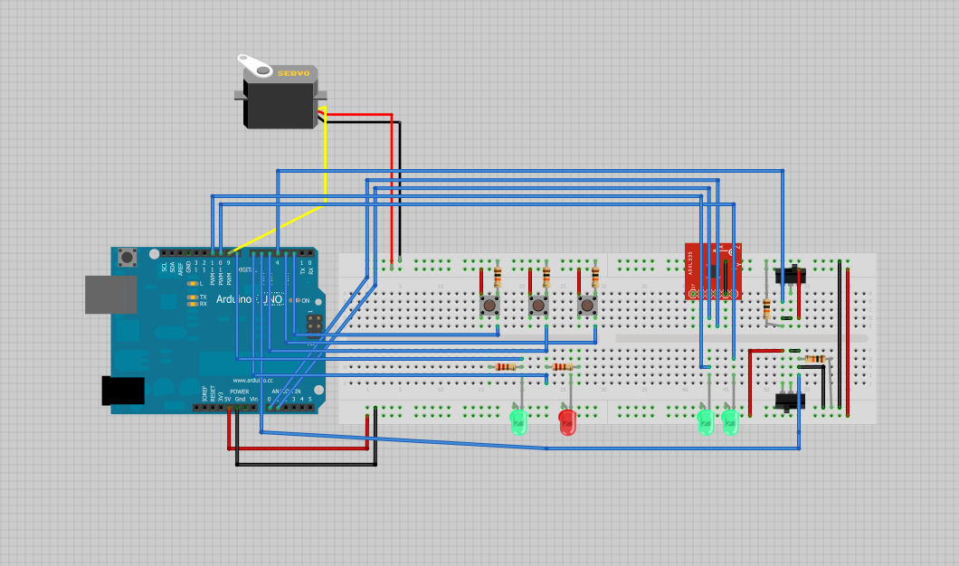
Here’s a picture of the fritzing document, which can be found: here
Let me preface this by saying that I am immensely proud of this work. The work up to here is very special and I can only hope that my work going forward is as good as this.
So I’m calling this the “Final Static Prototype” because it’s pretty damn complete for being prototype and it does not move. I intend on making a moving, non-flying prototype sometime in the future. Let’s start out with the video:
Now an explanation for each of the components starting with the controller.
It’s pretty much the same deal I’ve been using this entire time. The program works as follows.
1. The computer sends a delay value and a cycle number
2. The arduino receives that data
3. The arduino sends the debug switch value, the x and y values of the joystick and the pot value.
4. The program renders that information on the program.
Here’s the controller’s source:
//include/define
#include &lt;string.h&gt; // we'll need this for subString
#define MAX_STRING_LEN 20 // like 3 lines above, change as needed.
//Mux control pins
int s0 = 8;
int s1 = 9;
int s2 = 10;
int s3 = 11;
int SIG_pin = 0;
//Shift Register Pins
int SER_Pin = 5; //pin 14 on the 75HC595
int RCLK_Pin = 6; //pin 12 on the 75HC595
int SRCLK_Pin = 7; //pin 11 on the 75HC595
#define number_of_74hc595s 1 //How many of the shift registers - change this
#define numOfRegisterPins number_of_74hc595s * 8 //do not touch
boolean registers[numOfRegisterPins];
//serial stuff
const char EOPmarker = '.'; //This is the end of packet marker
char serialbuf[32]; //This gives the incoming serial some room. Change it if you want a longer incoming.
//other pin setup
int joystick_x;
int joystick_y;
int pot_1;
int debug_switch = 4;
//vars
int sample_delay;
int cycle_number;
void setup(){
//mux setup
pinMode(s0, OUTPUT);
pinMode(s1, OUTPUT);
pinMode(s2, OUTPUT);
pinMode(s3, OUTPUT);
digitalWrite(s0, LOW);
digitalWrite(s1, LOW);
digitalWrite(s2, LOW);
digitalWrite(s3, LOW);
//shift register setup
pinMode(SER_Pin, OUTPUT);
pinMode(RCLK_Pin, OUTPUT);
pinMode(SRCLK_Pin, OUTPUT);
pinMode(0, INPUT);
clearRegisters();
writeRegisters();
//other pin setup
pinMode(debug_switch, INPUT);
Serial.begin(115200);
}
void loop(){ //start of main loop -------------------------------------------
//delay(25);
pin_remap();
if (Serial.available() &gt; 0) {
static int bufpos = 0;
char inchar = Serial.read();
if (inchar != EOPmarker) {
serialbuf[bufpos] = inchar;
bufpos++;
}
else {
serialbuf[bufpos] = 0; //restart the buff
bufpos = 0; //restart the position of the buff
sample_delay = atoi(subStr(serialbuf, &quot;,&quot; , 1));
cycle_number = atoi(subStr(serialbuf, &quot;,&quot; , 2));
serial_handshake();
//delay(100);
}
}
delay(sample_delay);
} //end of main loop --------------------------------------------------------
//start of logic functions ------------------------------------------------
void serial_output_deploy(){
Serial.print(&quot;0&quot;);
Serial.print(&quot;,&quot;);
Serial.print(joystick_x);
Serial.print(&quot;,&quot;);
Serial.print(joystick_y);
Serial.print(&quot;,&quot;);
Serial.print(pot_1);
Serial.print(&quot;,&quot;);
Serial.print(sample_delay);
Serial.print(&quot;,&quot;);
Serial.print(cycle_number);
Serial.println(&quot;&quot;);
}
void serial_output_debug(){
Serial.print(&quot;1&quot;);
Serial.print(&quot;, &quot;);
Serial.print(&quot;Joystick X Axis: &quot;);
Serial.print(joystick_x);
Serial.print(&quot; , &quot;);
Serial.print(&quot;Joystick Y Axis: &quot;);
Serial.print(joystick_y);
Serial.print(&quot; , &quot;);
Serial.print(&quot;Speed Potentiometer: &quot;);
Serial.print(pot_1);
Serial.print(&quot; , &quot;);
Serial.print(&quot;Amount of delay between cycles: &quot;);
Serial.print(sample_delay);
Serial.print(&quot; , &quot;);
Serial.print(&quot;Cycle Number:&quot;);
Serial.print(cycle_number);
Serial.println(&quot;&quot;);
}
void pin_remap(){
joystick_x = map(readMux(15), 0, 1023, 180, 0);
joystick_y = map(readMux(14), 0, 1023, 0, 180);
pot_1 = map(readMux(13), 0, 1023, 0, 179);
}
void serial_handshake(){
if (digitalRead(debug_switch) == HIGH){
serial_output_debug();
setRegisterPin(1, HIGH);
setRegisterPin(2, LOW);
writeRegisters();
}
if (digitalRead(debug_switch) == LOW){
serial_output_deploy();
setRegisterPin(2, HIGH);
setRegisterPin(1, LOW);
writeRegisters();
}
}
//end of logic functions --------------------------------------------------
void clearRegisters(){
for(int i = numOfRegisterPins - 1; i &gt;= 0; i--){
registers[i] = LOW;
}
}
void writeRegisters(){
digitalWrite(RCLK_Pin, LOW);
for(int i = numOfRegisterPins - 1; i &gt;= 0; i--){
digitalWrite(SRCLK_Pin, LOW);
int val = registers[i];
digitalWrite(SER_Pin, val);
digitalWrite(SRCLK_Pin, HIGH);
}
digitalWrite(RCLK_Pin, HIGH);
}
//set an individual pin HIGH or LOW
void setRegisterPin(int index, int value){
registers[index] = value;
}
int readMux(int channel){
int controlPin[] = {s0, s1, s2, s3};
int muxChannel[16][4]={
{0,0,0,0}, //channel 0
{1,0,0,0}, //channel 1
{0,1,0,0}, //channel 2
{1,1,0,0}, //channel 3
{0,0,1,0}, //channel 4
{1,0,1,0}, //channel 5
{0,1,1,0}, //channel 6
{1,1,1,0}, //channel 7
{0,0,0,1}, //channel 8
{1,0,0,1}, //channel 9
{0,1,0,1}, //channel 10
{1,1,0,1}, //channel 11
{0,0,1,1}, //channel 12
{1,0,1,1}, //channel 13
{0,1,1,1}, //channel 14
{1,1,1,1} //channel 15
};
//loop through the 4 sig
for(int i = 0; i &lt; 4; i ++){
digitalWrite(controlPin[i], muxChannel[channel][i]);
}
//read the value at the SIG pin
int val = analogRead(SIG_pin);
//return the value
return val;
}
char* subStr (char* input_string, char *separator, int segment_number) {
char *act, *sub, *ptr;
static char copy[MAX_STRING_LEN];
int i;
strcpy(copy, input_string);
for (i = 1, act = copy; i &lt;= segment_number; i++, act = NULL) {
sub = strtok_r(act, separator, &amp;ptr);
if (sub == NULL) break;
}
return sub;
}
Now for the output simulator (eventually the plane)
This works like the controller with the “handshake” protocol as described above, but it writes to the servos and then sends sensor values. Here’s that source:
//include/define
#include &lt;string.h&gt; // we'll need this for subString
#define MAX_STRING_LEN 20 // like 3 lines above, change as needed.
#include &lt;LiquidCrystal.h&gt; //we'll need this for the lcd
LiquidCrystal lcd(22, 24, 26, 28, 32, 34); //pins for the lcd, I set it up using the ladyada tutorial.
#include &lt;Servo.h&gt;
//inputs
int debug_switch = 7;
//outputs
Servo left_servo;
Servo right_servo;
Servo esc;
int esc_pwm = 6;
int debug_led = 11;
int deploy_led = 12;
//numbers
int left_servo_pos;
int right_servo_pos;
int current;
//serial stuff
const char EOPmarker = '.'; //This is the end of packet marker
char serialbuf[32]; //This gives the incoming serial some room. Change it if you want a longer incoming.
//shift register setup
int SER_Pin = 8; //pin 14 on the 75HC595
int RCLK_Pin = 9; //pin 12 on the 75HC595
int SRCLK_Pin = 10; //pin 11 on the 75HC595
#define number_of_74hc595s 1 //How many of the shift registers - change this
#define numOfRegisterPins number_of_74hc595s * 8 //do not touch
boolean registers[numOfRegisterPins];
void setup(){
//lcd.begin(16, 2);
left_servo.attach(3);
right_servo.attach(5);
esc.attach(6);
current = 0;
pinMode(debug_switch, INPUT);
pinMode(1, INPUT);
pinMode(debug_led, OUTPUT);
pinMode(deploy_led, OUTPUT);
pinMode(SER_Pin, OUTPUT);
pinMode(RCLK_Pin, OUTPUT);
pinMode(SRCLK_Pin, OUTPUT);
pinMode(esc_pwm, OUTPUT);
// for(int i = 0; i &lt; 180; i += 1){
// esc.write(i);
// Serial.println(i);
// delay(15);
// }
clearRegisters();
writeRegisters();
Serial.begin(115200); //changing this to other speeds has not been tested using this meathod
}
void loop() {
if (Serial.available() &gt; 0) {
//lcd.clear();
static int bufpos = 0;
char inchar = Serial.read();
if (inchar != EOPmarker) {
serialbuf[bufpos] = inchar;
bufpos++;
}
else {
serialbuf[bufpos] = 0; //restart the buff
bufpos = 0; //restart the position of the buff
if(digitalRead(debug_switch) == HIGH){
debug();
}
if(digitalRead(debug_switch) != HIGH){
deploy();
}
out_deploy();
}
}
}
// below is just function logic, which I do not fully understand. but it works.
char* subStr (char* input_string, char *separator, int segment_number) {
char *act, *sub, *ptr;
static char copy[MAX_STRING_LEN];
int i;
strcpy(copy, input_string);
for (i = 1, act = copy; i &lt;= segment_number; i++, act = NULL) {
sub = strtok_r(act, separator, &amp;ptr);
if (sub == NULL) break;
}
return sub;
}
void clearRegisters(){
for(int i = numOfRegisterPins - 1; i &gt;= 0; i--){
registers[i] = LOW;
}
}
void writeRegisters(){
digitalWrite(RCLK_Pin, LOW);
for(int i = numOfRegisterPins - 1; i &gt;= 0; i--){
digitalWrite(SRCLK_Pin, LOW);
int val = registers[i];
digitalWrite(SER_Pin, val);
digitalWrite(SRCLK_Pin, HIGH);
}
digitalWrite(RCLK_Pin, HIGH);
}
//set an individual pin HIGH or LOW
void setRegisterPin(int index, int value){
registers[index] = value;
}
void spinto(int target) {
//digitalWrite(led2, LOW);
while(current &gt; target){
Serial.println(current);
esc.write(current);
delay(15);
current--;
}
while(current &lt; target){
Serial.println(current);
esc.write(current);
delay(15);
current++;
}
}
void debug(){
setRegisterPin(2, HIGH);
setRegisterPin(1, LOW);
writeRegisters();
left_servo_pos = atoi(subStr(serialbuf, &quot;,&quot;, 1));
lcd.write(&quot;Lft Servo:&quot;);
lcd.write(subStr(serialbuf, &quot;,&quot;, 1)); //witres the first bit of content before the first comma (or other seperator) to the lcd
left_servo.write(left_servo_pos);
lcd.setCursor(0, 1);
right_servo_pos = atoi(subStr(serialbuf, &quot;,&quot;, 2));
lcd.write(&quot;Rgt Servo:&quot;); //this signifies that the first seperation has occured
lcd.write(subStr(serialbuf, &quot;,&quot;, 2)); //same thing as 2 lines above, but with the second parts. this can be repeated
right_servo.write(right_servo_pos);
analogWrite(esc_pwm, atoi(subStr(serialbuf, &quot;,&quot;, 3)));
}
void deploy(){
setRegisterPin(2, LOW);
setRegisterPin(1, HIGH);
writeRegisters();
left_servo.write(atoi(subStr(serialbuf, &quot;,&quot;, 1)));
right_servo.write(atoi(subStr(serialbuf, &quot;,&quot;, 2)));
analogWrite(esc_pwm, atoi(subStr(serialbuf, &quot;,&quot;, 3)));
}
void out_deploy(){
Serial.print(analogRead(0));
Serial.print(&quot;,&quot;);
Serial.print(analogRead(1));
Serial.print(&quot;,&quot;);
Serial.print(analogRead(2));
Serial.println(&quot;&quot;);
}
//esologic.com
//Thanks to http://arduino.cc/forum/index.php?topic=119429
The visual basic program which I’m calling “Vehicle Companion” can be found here in all of it’s glory. The picture below also shows the whole system.
Now all I need is the money to make this thing wireless because I’ve got a way to make it into a moving prototype using materials I already have. I’ll put a donate button somewhere on this website eventually if you want to help me out.
I’ve still got no idea what i’m going to name it. If you’ve got an idea in for the name, feel free to leave it in the comments. Actually on that note, If you’re reading this PLEASE leave a comment. I’ve had A LOT of bot traffic lately so i’m starting to really crack down on who’s a real reader or a bot.
So as you can see in the video above, I’ve gotten all 3 components working. I can use either joystick axis to control either the left or right servo independently. The potentiometer controls the value that is sent to the esc. As you can see by the code the esc signal is just a servo.write command. The controller code is identical to the last “Plane” post with the exception that the code mapped from the pot goes to 170 instead of 225. This is because I switched from a analogWrite() to a servo.write() signal.
Vehicle Code:
const char EOPmarker = '.';  //This is the end of packet marker
char serialbuf[32]; //This gives the incoming serial some room. Change it if you want a longer incoming.

#include <string.h> // we'll need this for subString
#define MAX_STRING_LEN 20 // like 3 lines above, change as needed.

#include <LiquidCrystal.h> //we'll need this for the lcd
LiquidCrystal lcd(7, 8, 9, 10, 11, 12); //pins for the lcd, I set it up using the ladyada tutorial.

#include <Servo.h>
Servo left_servo;
Servo right_servo;
Servo esc;
int esc_pwm = 6;

int left_servo_pos;
int right_servo_pos;
int current;

int prophot = 2;

int SER_Pin = 8;   //pin 14 on the 75HC595
int RCLK_Pin = 9;  //pin 12 on the 75HC595
int SRCLK_Pin = 10; //pin 11 on the 75HC595
#define number_of_74hc595s 1 //How many of the shift registers - change this
#define numOfRegisterPins number_of_74hc595s * 8 //do not touch
boolean registers[numOfRegisterPins];

void setup(){
  lcd.begin(16, 2);
  left_servo.attach(3);
  right_servo.attach(5);
  esc.attach(6);
  pinMode(prophot, INPUT);
  pinMode(esc_pwm, OUTPUT);

  current = 0;

  pinMode(SER_Pin, OUTPUT);
  pinMode(RCLK_Pin, OUTPUT);
  pinMode(SRCLK_Pin, OUTPUT);

  for(int i = 0; i < 180; i += 1){
    esc.write(i);
    Serial.println(i);
    delay(15);
  }
  esc.write(0);

  clearRegisters();
  writeRegisters();

  Serial.begin(9600); //changing this to other speeds has not been tested using this meathod
}

void loop() {

     setRegisterPin(1, HIGH);
     writeRegisters();

    if (Serial.available() > 0) { //makes sure something is ready to be read
      lcd.clear(); //clears for incoming stuff, won't clear if there isin't data to be read
      static int bufpos = 0; //starts the buffer back at the first position in the incoming serial.read
      char inchar = Serial.read(); //assigns one byte (as serial.read()'s only input one byte at a time
      if (inchar != EOPmarker) { //if the incoming character is not the byte that is the incoming package ender
        serialbuf[bufpos] = inchar; //the buffer position in the array get assigned to the current read
        bufpos++; //once that has happend the buffer advances, doing this over and over again until the end of package marker is read.
     }
      else { //once the end of package marker has been read
        serialbuf[bufpos] = 0; //restart the buff
         bufpos = 0; //restart the position of the buff

         left_servo_pos = atoi(subStr(serialbuf, ",", 1));
         setRegisterPin(1, HIGH);
         writeRegisters();
         left_servo.write(left_servo_pos);
         setRegisterPin(1, LOW);
         writeRegisters();

         lcd.setCursor(0, 1);

         right_servo_pos = atoi(subStr(serialbuf, ",", 2));
         setRegisterPin(3, HIGH);
         writeRegisters();
         right_servo.write(right_servo_pos);
         setRegisterPin(3, LOW);
         writeRegisters();

         if (digitalRead(prophot) == HIGH){
           esc.write(atoi(subStr(serialbuf, ",", 3)));
         }
         if (digitalRead(prophot) == LOW){
           esc.write(0);
         }
      }
   }
}

// below is just function logic, which I do not fully understand. but it works.
char* subStr (char* input_string, char *separator, int segment_number) {
 char *act, *sub, *ptr;
 static char copy[MAX_STRING_LEN];
 int i;

 strcpy(copy, input_string);

for (i = 1, act = copy; i <= segment_number; i++, act = NULL) {

 sub = strtok_r(act, separator, &ptr);
 if (sub == NULL) break;
 }
 return sub;
}

void clearRegisters(){
  for(int i = numOfRegisterPins - 1; i >=  0; i--){
     registers[i] = LOW;
  }
}

void writeRegisters(){
  digitalWrite(RCLK_Pin, LOW);
  for(int i = numOfRegisterPins - 1; i >=  0; i--){
    digitalWrite(SRCLK_Pin, LOW);
    int val = registers[i];
    digitalWrite(SER_Pin, val);
    digitalWrite(SRCLK_Pin, HIGH);
  }
  digitalWrite(RCLK_Pin, HIGH);
}

//set an individual pin HIGH or LOW
void setRegisterPin(int index, int value){
  registers[index] = value;
}

void spinto(int target) {

  setRegisterPin(3, HIGH);
  writeRegisters();

  while(current > target){
    //Serial.println(current);
    esc.write(current);
    delay(15);
    current--;
  }

  while(current < target){
    //Serial.println(current);
    esc.write(current);
    delay(15);
    current++;
  }

  setRegisterPin(3, LOW);
  writeRegisters();

}

//esologic.com
//Thanks to http://arduino.cc/forum/index.php?topic=119429
I’ve also been starting to think about how i’m going to take this thing to the next stage. The parts list still exists here: https://docs.google.com/spreadsheet/ccc?key=0AqD_oicSxsvmdFlPU1VPSkt6aHpoa0hqSEgwdDE2RGc if you want to check out what i’ve done so far. I’m starting to consider materials to make the body out of. Right now the main contendor is making a frame out of aluminum dowels welded together. I’ve got a friend who can weld aluminum so assembling the frame won’t be an issue. If I go with this option, i’ll be able to cleanly mount things to the vehicle itself, and not have to worry about things splitting or cracking. It will also be heavier than if I were to go with an all foam body.
I’ve also been considering what i’m going to get for a camera for this thing. As one of the goals for this was to be able to take really nice areal videos. I’ve tentatively landed on a camera called the HackHD. The thing that’s most attractive about it is that it can do 1080p video capture AND composite video output at the same time. This is great because my original plan was to have 2 cameras – one for HD video capture, and one to transmit back to my computer. The only problem is it’s price. I could easily just hack one of those HD keychain cameras to make it operable via micro controller – but I would need to use two cameras which could be cheaper after all but powering two separate cameras would be pretty difficult.
I need to wirelessly communicate with the vehicle as well. If you look through some of the videos on my old youtube channel you can see a little RC tank that communicated via bluetooth, so I’ve got a shred of experience with homebrew wireless. Again, I’ve tentatively landed on a solution. I’ve concluded that using an Xbee system would be the most flexible while maintaining stability. It can be used as a long-range serial TxRx pipe which is what i’m prototyping with now, so the whole code’s built around that. I’d be using the XBee 1mW Wire Antenna – Series 1 (802.15.4) for the transmitter, as it’s easy to power and has an omnidirectional antenna with a range of 1 mile. While I may not be flying a mile away, I’d like to have the flexibility. I could fly in the woods, in the snow, or in the fog. To connect the xbee to the Arduino I’d probably use the SainSmart XBee USB Adapter because it’s got the UART broken out. I could use the same board to connect it to the pc as well. I could make the whole system work for around 72 dollars, which is a little high but I really want it to work well.
I’ll cover powering it in another post, but I think the next thing I get is going to be the wireless stuff. I’ve been thinking a lot about how i’m going to proto a moving vehicle, I’m thinking of some kind of fan-boat thing. Or a 3 wheeled fan propelled car.
So here are all 3 prongs of the plane code thus far. This sends data to the visual basic program, then to the visual basic program where it gets interpreted and then sent to the plane simulator Arduino. Where it is written to servos and and led.
Arduino Controller:
//Mux control pins</pre>
int s0 = 8;
int s1 = 9;
int s2 = 10;
int s3 = 11;
int SIG_pin = 0;

//Shift Register Pins
int SER_Pin = 5; //pin 14 on the 75HC595
int RCLK_Pin = 6; //pin 12 on the 75HC595
int SRCLK_Pin = 7; //pin 11 on the 75HC595
#define number_of_74hc595s 1 //How many of the shift registers - change this
#define numOfRegisterPins number_of_74hc595s * 8 //do not touch
boolean registers[numOfRegisterPins];

//other pin setup
int joystick_x;
int joystick_y;
int pot_1;

int debug_switch = 4;

void setup(){
 //mux setup
 pinMode(s0, OUTPUT);
 pinMode(s1, OUTPUT);
 pinMode(s2, OUTPUT);
 pinMode(s3, OUTPUT);
 digitalWrite(s0, LOW);
 digitalWrite(s1, LOW);
 digitalWrite(s2, LOW);
 digitalWrite(s3, LOW);

 //shift register setup
 pinMode(SER_Pin, OUTPUT);
 pinMode(RCLK_Pin, OUTPUT);
 pinMode(SRCLK_Pin, OUTPUT);
 pinMode(0, INPUT);
 clearRegisters();
 writeRegisters();

 //other pin setup
 pinMode(debug_switch, INPUT);

 Serial.begin(9600);
}
void loop(){ //start of main loop -------------------------------------------
 delay(25);
 pin_remap();

 if (digitalRead(debug_switch) == HIGH){
 serial_output_debug();
 setRegisterPin(1, HIGH);
 setRegisterPin(2, LOW);
 writeRegisters();
 }

 if (digitalRead(debug_switch) == LOW){
 serial_output();
 setRegisterPin(2, HIGH);
 setRegisterPin(1, LOW);
 writeRegisters();
 }

} //end of main loop --------------------------------------------------------
 //start of logic functions ------------------------------------------------
void serial_output(){
 Serial.print(joystick_x);
 Serial.print(" ");
 Serial.print(joystick_y);
 Serial.print(" ");
 Serial.print(pot_1);

 Serial.println("");
}

void serial_output_debug(){
 Serial.print("Joystick X Axis: ");
 Serial.print(joystick_x);
 Serial.print(" , ");
 Serial.print("Joystick Y Axis: ");
 Serial.print(joystick_y);
 Serial.print(" , ");
 Serial.print("Speed Potentiometer: ");
 Serial.print(pot_1);

 Serial.println("");
}

void pin_remap(){
 joystick_x = map(readMux(15), 0, 1023, 180, 0);
 joystick_y = map(readMux(14), 0, 1023, 0, 180);
 pot_1 = map(readMux(13), 0, 1023, 0, 255);
}
 //end of logic functions --------------------------------------------------
void clearRegisters(){
 for(int i = numOfRegisterPins - 1; i >= 0; i--){
 registers[i] = LOW;
 }
}

void writeRegisters(){
 digitalWrite(RCLK_Pin, LOW);
 for(int i = numOfRegisterPins - 1; i >= 0; i--){
 digitalWrite(SRCLK_Pin, LOW);
 int val = registers[i];
 digitalWrite(SER_Pin, val);
 digitalWrite(SRCLK_Pin, HIGH);
 }
 digitalWrite(RCLK_Pin, HIGH);
}

//set an individual pin HIGH or LOW
void setRegisterPin(int index, int value){
 registers[index] = value;
}

int readMux(int channel){
 int controlPin[] = {s0, s1, s2, s3};
 int muxChannel[16][4]={
 {0,0,0,0}, //channel 0
 {1,0,0,0}, //channel 1
 {0,1,0,0}, //channel 2
 {1,1,0,0}, //channel 3
 {0,0,1,0}, //channel 4
 {1,0,1,0}, //channel 5
 {0,1,1,0}, //channel 6
 {1,1,1,0}, //channel 7
 {0,0,0,1}, //channel 8
 {1,0,0,1}, //channel 9
 {0,1,0,1}, //channel 10
 {1,1,0,1}, //channel 11
 {0,0,1,1}, //channel 12
 {1,0,1,1}, //channel 13
 {0,1,1,1}, //channel 14
 {1,1,1,1} //channel 15
 };

//loop through the 4 sig
 for(int i = 0; i < 4; i ++){
 digitalWrite(controlPin[i], muxChannel[channel][i]);
 }

//read the value at the SIG pin
 int val = analogRead(SIG_pin);

//return the value
 return val;
}
<pre>
Arduino Vehicle:
</pre>
const char EOPmarker = '.'; //This is the end of packet marker
char serialbuf[32]; //This gives the incoming serial some room. Change it if you want a longer incoming.
#include <string.h> // we'll need this for subString
#define MAX_STRING_LEN 20 // like 3 lines above, change as needed.
#include <LiquidCrystal.h> //we'll need this for the lcd
LiquidCrystal lcd(7, 8, 9, 10, 11, 12); //pins for the lcd, I set it up using the ladyada tutorial.
#include <Servo.h>
Servo left_servo;
Servo right_servo;
int esc_pwm = 6;
int left_servo_pos;
int right_servo_pos;
void setup(){
lcd.begin(16, 2);
left_servo.attach(3);
right_servo.attach(5);
pinMode(esc_pwm, OUTPUT);
Serial.begin(9600); //changing this to other speeds has not been tested using this meathod
}
void loop() {
if (Serial.available() > 0) { //makes sure something is ready to be read
lcd.clear(); //clears for incoming stuff, won't clear if there isin't data to be read
static int bufpos = 0; //starts the buffer back at the first position in the incoming serial.read
char inchar = Serial.read(); //assigns one byte (as serial.read()'s only input one byte at a time
if (inchar != EOPmarker) { //if the incoming character is not the byte that is the incoming package ender
serialbuf[bufpos] = inchar; //the buffer position in the array get assigned to the current read
bufpos++; //once that has happend the buffer advances, doing this over and over again until the end of package marker is read.
}
else { //once the end of package marker has been read
serialbuf[bufpos] = 0; //restart the buff
bufpos = 0; //restart the position of the buff
left_servo_pos = atoi(subStr(serialbuf, ",", 1));
lcd.write("Lft Servo:");
lcd.write(subStr(serialbuf, ",", 1)); //witres the first bit of content before the first comma (or other seperator) to the lcd
left_servo.write(left_servo_pos);
lcd.setCursor(0, 1);
right_servo_pos = atoi(subStr(serialbuf, ",", 2));
lcd.write("Rgt Servo:"); //this signifies that the first seperation has occured
lcd.write(subStr(serialbuf, ",", 2)); //same thing as 2 lines above, but with the second parts. this can be repeated
right_servo.write(right_servo_pos);
analogWrite(esc_pwm, atoi(subStr(serialbuf, ",", 3)));
}
}
}
// below is just function logic, which I do not fully understand. but it works.
char* subStr (char* input_string, char *separator, int segment_number) {
char *act, *sub, *ptr;
static char copy[MAX_STRING_LEN];
int i;
strcpy(copy, input_string);
for (i = 1, act = copy; i <= segment_number; i++, act = NULL) {
sub = strtok_r(act, separator, &ptr);
if (sub == NULL) break;
}
return sub;
}
//esologic.com
//Thanks to http://arduino.cc/forum/index.php?topic=119429
<pre>
Ever since I posted this back in January I’ve been collecting ideas and information on how to make something like the craft pictured in the video and related ones.
The tenative parts list can be found here, but there’s an analog accelerometer, an esc + brushless motor combo, and a battery array so far.
As for wireless, that’s the one area of this project that I’ve done no research on at all. I’m probably going to use a long range bluetooth serial connection, or an xbee serial connection. No matter what it’s going to be serial, as that’s what I’m most familiar with.
So far I’ve proto’d the controller and written the framework for the visual basic program and some of the controller arduino side of the program.
Here’s the video of what I’ve done so far, as you can see the trackbar visualizes reallly nicely. and i’m using the split function and my knowledge of arrays to separate x and y resistance values from the joystick:
http://youtu.be/qTN9DqKTL9M
As you can probably also tell, there’s no name for the project yet, if you think of something let me know!