
First of all, here’s a video of this device in action.
So things are really starting to take shape with the plane (still unnamed…) and I’ve got a really solid framework for an auto-balancing system. Basically the program below maps the x value given from the ADXL335 to a value from 1-180 on the servo. A lot of this code is for debug, but that portion can be switched off.
</pre>
#include <Servo.h>

Servo myservo;

int raw_val;
int ref_val;
int mid_val = 336;

int left_tilt = 260;
int rght_tilt = 405;

int min_switch = 2;
int max_switch = 3;
int mid_switch = 5;
int mode_switch = 4;

int debug_switch = 6;

int bounds_LED = 10;
int mid_LED = 11;

int debug_LED = 7;
int normal_LED = 8;

void setup(){

 pinMode(min_switch, INPUT);
 pinMode(max_switch, INPUT);
 pinMode(mid_switch, INPUT);
 pinMode(debug_switch, INPUT);

 pinMode(mode_switch, INPUT);

 pinMode(bounds_LED, OUTPUT);
 pinMode(mid_LED, OUTPUT);

 pinMode(debug_LED, OUTPUT);
 pinMode(normal_LED, OUTPUT);

 Serial.begin(9600);
 myservo.attach(9);
}

void loop(){
 if (digitalRead(debug_switch) == HIGH) {

 digitalWrite(debug_LED, HIGH);
 digitalWrite(normal_LED, LOW);

 raw_val = analogRead(0);

 if (digitalRead(mode_switch) == HIGH) {

 digitalWrite(bounds_LED, HIGH);
 digitalWrite(mid_LED, LOW);

 Serial.print("BOUNDS MODE: ");

 ref_val = map(raw_val, left_tilt, rght_tilt, 0, 180);

 myservo.write(ref_val);

 if (digitalRead(min_switch) == HIGH){
 Serial.print("LEFT HGH");
 left_tilt = raw_val;
 }

 if (digitalRead(min_switch) == LOW){
 Serial.print("LEFT LOW");
 }

 Serial.print(" , ");

 if (digitalRead(max_switch) == HIGH){
 Serial.print("RGHT HGH");
 rght_tilt = raw_val;
 }

 if (digitalRead(max_switch) == LOW){
 Serial.print("RHGT LOW");
 }

 Serial.print(" , ");

 Serial.print("Left Tilt: ");
 Serial.print(left_tilt);

 Serial.print("Rght Tilt: ");
 Serial.print(rght_tilt);

 }

 if (digitalRead(mode_switch) == LOW) {

 Serial.print("MID MODE:");

 if (digitalRead(mid_switch) == HIGH){
 mid_val = raw_val;
 }

 int MLeft_val = mid_val - 75;
 int MRght_val = mid_val + 75;

 ref_val = map(raw_val, MLeft_val, MRght_val, 0, 180);
 myservo.write(ref_val);

 digitalWrite(bounds_LED, LOW);
 digitalWrite(mid_LED, HIGH);

 Serial.print(" , ");
 Serial.print("Left Most Value: ");
 Serial.print(MLeft_val);
 Serial.print(" , ");
 Serial.print("Rght Most Value: ");
 Serial.print(MRght_val);
 Serial.print(" , ");
 Serial.print(mid_val);

 }
 Serial.print(" , ");
 Serial.print("Raw Value: ");
 Serial.print(raw_val);
 Serial.print(" , ");
 Serial.print("Current Servo Value: ");
 Serial.print(ref_val);

 Serial.println("");
}

 if (digitalRead(debug_switch) == LOW) {

 digitalWrite(debug_LED, LOW);
 digitalWrite(normal_LED, HIGH);

 raw_val = analogRead(0);
 if (digitalRead(mode_switch) == HIGH) {
 digitalWrite(bounds_LED, HIGH);
 digitalWrite(mid_LED, LOW);
 ref_val = map(raw_val, left_tilt, rght_tilt, 0, 180);
 myservo.write(ref_val);
 if (digitalRead(min_switch) == HIGH){
 left_tilt = raw_val;
 }
 if (digitalRead(max_switch) == HIGH){
 rght_tilt = raw_val;
 }
 }

 if (digitalRead(mode_switch) == LOW) {
 if (digitalRead(mid_switch) == HIGH){
 mid_val = raw_val;
 }<a href="https://esologic.com/wp-content/uploads/2012/12/2012-12-27_14-20-51_644.jpg">
</a>
 int MLeft_val = mid_val - 75;
 int MRght_val = mid_val + 75;
 ref_val = map(raw_val, MLeft_val, MRght_val, 0, 180);
 myservo.write(ref_val);
 digitalWrite(bounds_LED, LOW);
 digitalWrite(mid_LED, HIGH);
 }
 }
}
Sorry for the lack of comments in this code, it’s pretty intuitive though, at it’s core its all about the map command.
Here’s a picture of what my desk looks like:

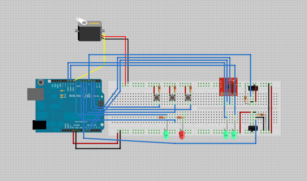
Here’s a picture of the fritzing document, which can be found: here
Thanks for reading!